Processor: MSP430F5172
I am wondering what is the most accurate way to achieve rising-edge synchronization between two CCR output modules from two different timers when their timebases are different. Ideally I want the edges to occur within a few MCLKs of each other, preferably < 10. Bear in mind this post is a gross simplification of the overall project, but it gets the basic idea across. Allow me to first illustrate with a diagram:
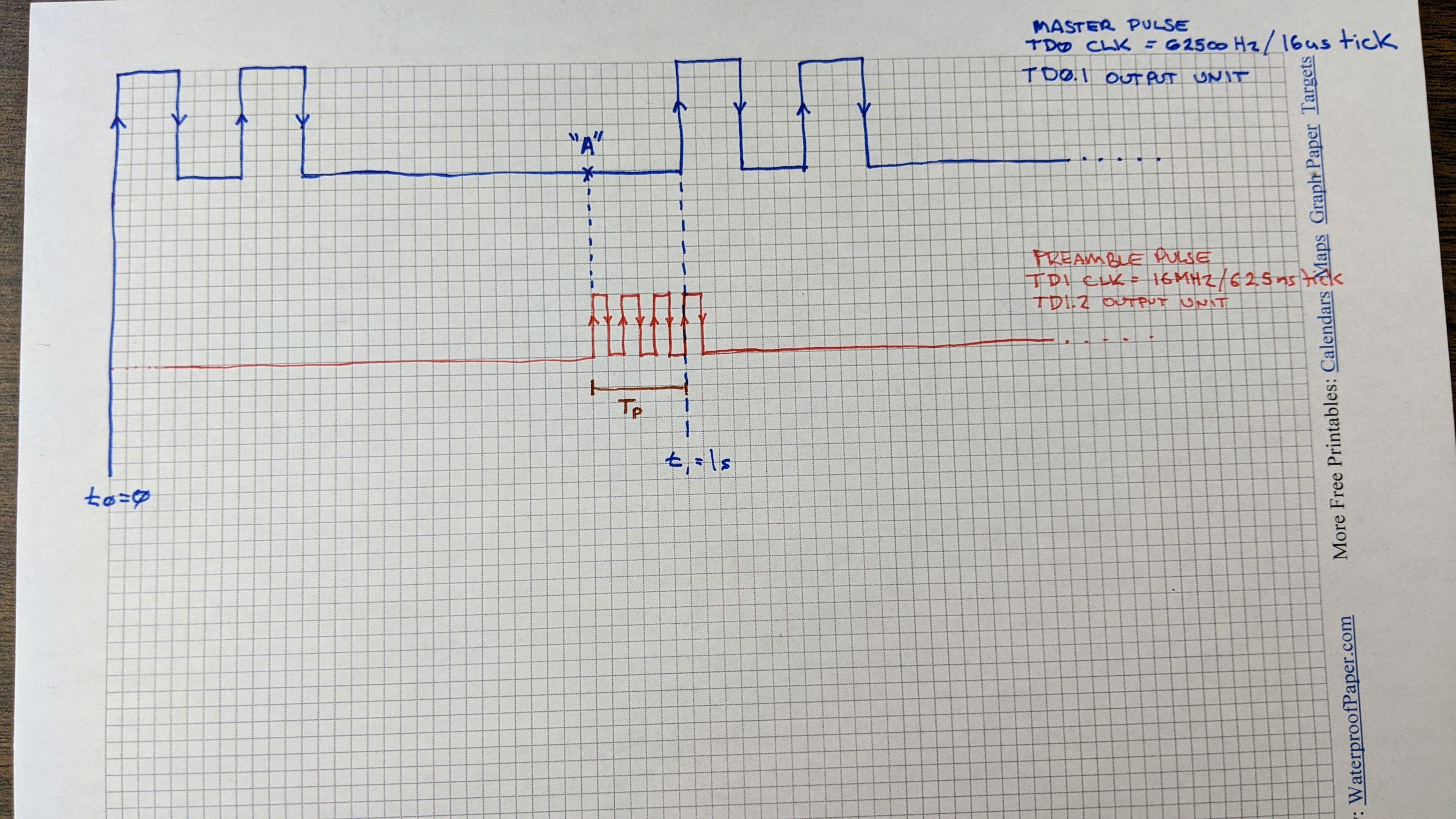
The top pulse train is generated by using TD0 and TD0CCR1 along with its output compare unit configured to output on pin TD0.1 TD0 is configured to operate from a 62500kHz clock generated through the usual clock dividers. The pulse train itself has a period of 1 second; therefore, a total of 62500 clock ticks of TD0 occur during any single period of this pulse train. The pulse train timing is generated by (1) an array that holds intervals (2) a const that holds the number of edges to know when we are at the end of the pattern (3) an index of where we are in the timing array and (4) a variable holding the current pulse state being HIGH or LOW (5) the ISR which increments the interval to be timed and modifies TD0CCR1
Here is some of my example code showing how the top pulse train gets generated:
#include <msp430f5172.h>
#include <main.h>

// ******************************************************************************************** //
// OUTPUT PULSE TIMINGS
// ACLK @ 500kHz * 1/8 divider = 16us/tick
//
// NOTE:   TD0/TD1 set for CONTINUOUS mode
// pulseTiming_master[] times alternately HIGH period, LOW period, HIGH period, LOW period, etc.
//
// NOTE:  All element in this array should add up to 1s / 16us == 62500
// ****************************************************************************************** //
// 75ms ON, 100ms OFF, 75ms ON, 700ms OFF
const       uint16_t        pulseTiming_master[4]       = { 4688, 6250, 4688, 46874 };
const       uint8_t         numEdges_master             = 4;
volatile    uint8_t         pulseIdx_master             = 0;
volatile    pulseState_t    curPulseVal_master          = LOW;


// This isr triggers when TD0R counts to TD0CCR1-6
// OUTMOD_1 -->   SET the pin in hardware output unit
// OUTMOD_5 --> RESET the pin in hardware output unit
// PJ.6     --> TD0.1 -->  output pin for  pulse
#pragma vector = TIMER0_D1_VECTOR
__interrupt void Timer0_D1_ISR(void)
{
    switch( TD0IV )
    {
        case 0:                                     // No interrupt; reserved for CCR0
            break;
        case 2:                                     // TD0CCR1

            if( curPulseVal_master == LOW )         // ... pin just flipped HIGH, then we enter this isr...
            {
                // Pin is SET HIGH now, next interrupt want to RESET IT LOW
                TD0CCTL1           = OUTMOD_5 | CCIE;
                curPulseVal_master = HIGH;
            }
            else
            if( curPulseVal_master == HIGH )        // ... pin just flipped LOW, then enter this isr...
            {
                // Pin is RESET LOW now, next interrupt want to SET IT HIGH
                TD0CCTL1           = OUTMOD_1 | CCIE;
                curPulseVal_master = LOW;
            }

            // Update the interval to time
            TD0CCR1 = TD0R + pulseTiming_master[pulseIdx_master];
            // Update the index of the pulse timing array ...
            if( pulseIdx_master < numEdges_master - 1 )         pulseIdx_master++;
            else                                                pulseIdx_master = 0;

            break;
        case 4:                                     // TD0CCR2
            break;

        default:  __never_executed();

    }
}


int main(void)
{
    WDTCTL = WDTPW | WDTHOLD;	// stop watchdog timer

    // ASSUME clock system is already configured with MCLK = 16MHz, ACLK = 500kHz ... not showing this here

    // Stop timer & clear divider
    TD0CTL0 = TDCLR;
    TD0R    = 0;
    // TD0 uses ACLK @ 500kHz (2us) as input clock; input divider = 8; continuous mode; 16-bit; individual groups;
    TD0CTL0 = TDSSEL__ACLK | ID__8 | CNTL__16 | SHR_0 | TDCLGRP_0;
    // Expansion div = 1
    TD0CTL1 = TDIDEX__1;


    // Make sure pulse timings start from initial conditions
    pulseIdx_master    = 0;
    curPulseVal_master = LOW;

    // OUT signal affected when TD0R "counts to" TD0CCR1
    TD0R               = 0xFFFF;
    TD0CCR1            = 0;

    // Immediate load; Start output as a SET operation; enable the interrupt
    TD0CCTL1          |= CLLD_0 | OUTMOD_1 | CCIE;

    // Start the timer running
    TD0CTL0           |= MC__CONTINUOUS;


    __bis_SR_register(GIE);               // Enable global interrupts

    while(1)
    {

    }
    return 0;
}
OK so the overall idea ( referring to the illustration ) is to provide a preamble of sorts to the first rising edge of that master pulse ( illustrated in BLUE ) The preamble ( illustrated in RED ) consists of some arbitrary number of pulses prior to that first master rising edge ( these pulses will vary in the end application in high/low time as well as quantity ) The last rising edge of the preamble must occur at the same time, or very close to, the rising edge of the master pulse.
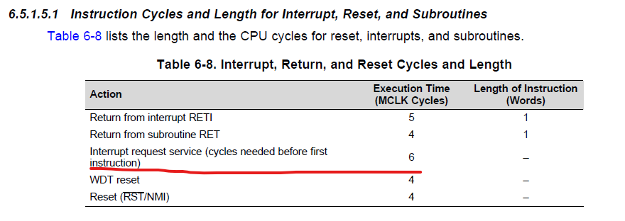
The complication to this is that this preamble pulse operates from a different timer, TD1, and that TD1 is clocked at 16MHz. This pulse is under the control of TD1 and uses the TD1CCR2 output unit, outputting pulses on pin TD1.2 From the illustration, I can do some temporal math to determine where point "A" is but I don't know what to do in software when "A" occurs. Moreover, I am unsure how to handle the long time difference between when TD0R rolls over and when TD1R rolls over. In practice, the preamble pulses will have high/low times on the order of 32 - 128us ... necessitating this 16MHz input clock to TD1.
The method to generate this preamble from TD1 is the same or similar to the master pulse, i.e., using the output compare unit and then in the ISR reading the values from a linear array to time the next interval until the end of the preamble pattern is reached. In this sense, the preamble itself has a period equal to that of the master; in the simple example here, 1 second.
Reaching out to all timer experts here at the MSP430 forums: If you had to achieve what I've described above, how would you do it? Is there a way to have the edges of master/preamble pulses line up exactly? If not, what would I do in software to achieve close synchronization as described in this post?