This thread has been locked.

If you have a related question, please click the "Ask a related question" button in the top right corner. The newly created question will be automatically linked to this question.

EVM430-FR6047: SPI interface sample program

Part Number: EVM430-FR6047
Other Parts Discussed in Thread: MSP430FR6047

I'm trying to connect an EVM430-FR6047 to an Adafruit RFM9x using the SPI interface, but I'm not finding any libraries/code samples. I've been able to use Arduino libraries from Adafruit/RadioHead (https://github.com/adafruit/RadioHead) . Please pass along any information you may have.

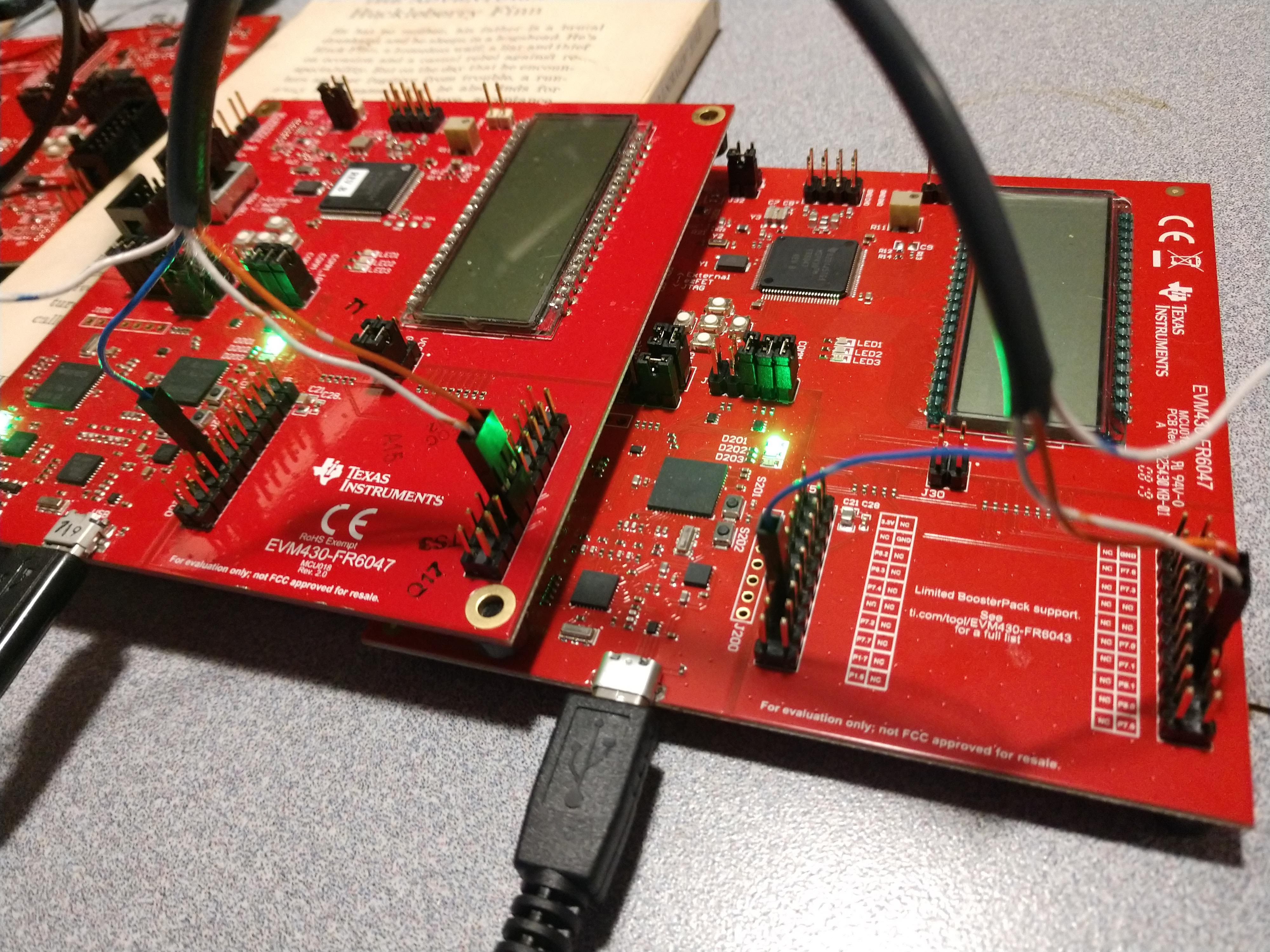
In the meantime, I'm trying to make sure that I'm understanding the SPI interface on the EVM430-FR6047 by using one of the code samples from TI: msp430fr60x7_euscia0_spi_09. For testing purposes, I have two EVM430-FR6047s connected together using a three-wire SPI connection:

Board #1:           Board #2:

P7.0 SPI_MOSI  -->  P7.1 SPI_MISO

P7.1 SPI_MISO  -->  P7.0 SPI_MOSI

P7.2 SPI_SCLK  -->  P7.1 SPI_SCLK

I'm definitely not an expert on this stuff, but my understanding is that I should be able to send data from one board to the other and use the debugger to see the result. The program compiles and runs and the ISR triggers for both the TX and RX signals, but the data received (RXData) is always 0. 

Here's the code:

#include <msp430fr6047.h>

volatile unsigned char RXData = 0;
volatile unsigned char TXData;

int main(void)
{
    WDTCTL = WDTPW | WDTHOLD; // Stop watchdog timer

    // Configure GPIO
    P7SEL1 &= ~BIT0 | ~BIT2 | ~BIT3; // USCI_A1 SCLK, MOSI, MISO pins
    P7SEL0 |= BIT0 | BIT2 | BIT3;

    PJSEL0 |= BIT4 | BIT5; // For XT1

    // Disable the GPIO power-on default high-impedance mode to activate
    // previously configured port settings
    PM5CTL0 &= ~LOCKLPM5;

    // XT1 Setup
    CSCTL0_H = CSKEY_H; // Unlock CS registers
    CSCTL1 = DCOFSEL_0; // Set DCO to 1MHz
    CSCTL2 = SELA__LFXTCLK | SELS__DCOCLK | SELM__DCOCLK;
    CSCTL3 = DIVA__1 | DIVS__1 | DIVM__1; // set all dividers
    CSCTL4 &= ~LFXTOFF;
    do
    {
        CSCTL5 &= ~LFXTOFFG; // Clear XT1 fault flag
        SFRIFG1 &= ~OFIFG;
    } while (SFRIFG1 & OFIFG); // Test oscillator fault flag
    CSCTL0_H = 0; // Lock CS registers

    // Configure USCI_A0 for SPI operation
    UCA1CTLW0 = UCSWRST; // **Put state machine in reset**
    UCA1CTLW0 |= UCMST | UCSYNC | UCCKPL | UCMSB; // 3-pin, 8-bit SPI master
    // Clock polarity high, MSB
    UCA1CTLW0 |= UCSSEL__ACLK; // ACLK
    UCA1BRW = 0x02; // /2
    UCA1MCTLW = 0; // No modulation
    UCA1CTLW0 &= ~UCSWRST; // **Initialize USCI state machine**
    UCA1IE |= UCRXIE; // Enable USCI_A0 RX interrupt
    TXData = 0x1; // Holds TX data

    while(1)
    {
        UCA1IE |= UCTXIE;
        __bis_SR_register(LPM0_bits | GIE); // CPU off, enable interrupts
        __delay_cycles(2000); // Delay before next transmission
        TXData++; // Increment transmit data
    }
}

#if defined(__TI_COMPILER_VERSION__) || defined(__IAR_SYSTEMS_ICC__)
#pragma vector=EUSCI_A1_VECTOR
__interrupt void USCI_A0_ISR(void)
#elif defined(__GNUC__)
void __attribute__ ((interrupt(EUSCI_A1_VECTOR))) USCI_A1_ISR (void)
#else
#error Compiler not supported!
#endif
{
    switch(__even_in_range(UCA1IV, USCI_SPI_UCTXIFG))
    {
    case USCI_NONE: break;
    case USCI_SPI_UCRXIFG:
        RXData = UCA1RXBUF;
        UCA1IFG &= ~UCRXIFG;
        __bic_SR_register_on_exit(LPM0_bits); // Wake up to setup next TX
        break;
    case USCI_SPI_UCTXIFG:
        UCA1TXBUF = TXData; // Transmit characters
        UCA1IE &= ~UCTXIE;
        break;
    default: break;
    }
}

I made a few changes from the original version of this program because it seemed to be written for some other EVM board. The original code used P1.0, P1.2, and P1.3 for SPI_SCLK, SPI_MOSI, SPI_MISO (in that order). The EVM430-FR6047 user guide shows P7.2, P7.0, and P7.1 for those connections. The other modification was to replace #include <msp430.h> with #include <msp430fr6047.h>. 

I actually tried several combinations:

  • Using the original code for P1.0, P1.2, and P1.3
  • Using the original #include <msp430.h>

A similar test using the UART interface worked perfectly with the sample msp430fr60x7_euscia0_uart_03.c, so I'm not understanding why the SPI interface isn't working. Here's the physical setup:
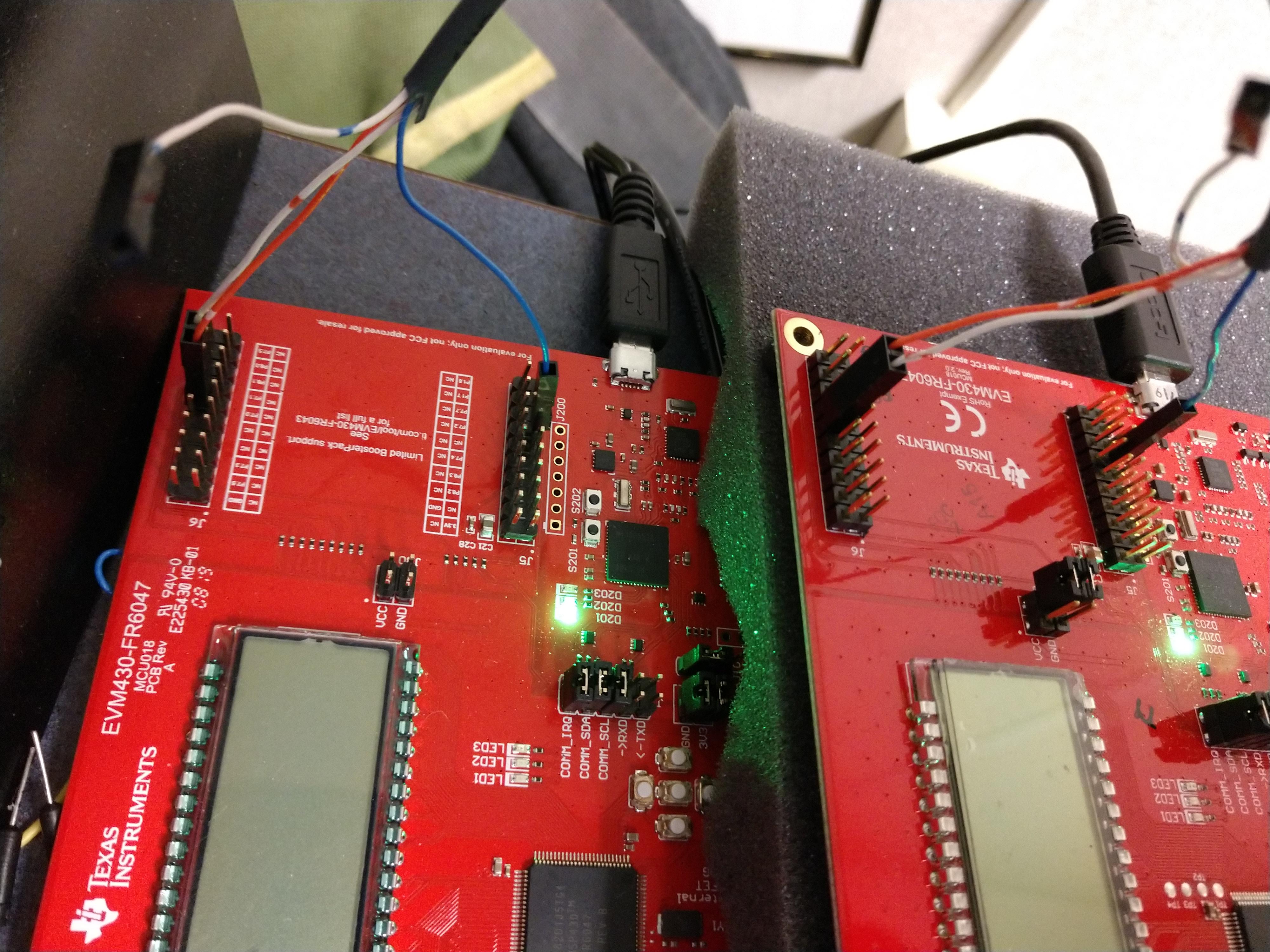
Thanks!

  • >  UCA1CTLW0 |= UCMST | UCSYNC | UCCKPL | UCMSB;

    Only one side can be the master. The master is the one that drives SCK. If both sides drive the clock, you get a bunch of bus contention and it's hard to say what the result is.

    Not that it matters, since the master doesn't actually look at the clock -- when it's done its 8 pulses it stops. That's why your transaction completes (on each side), even though nothing was really communicated.

    So you need to designate one side as the slave (UCMST=0) and connect MISO to MISO and MOSI to MOSI. The slave will act on the clock driven by the master.

  • Thanks for your quick response - it helped me understand the SPI concepts a lot better. Unfortunately, I still can't get the interface to receive data. In my new setup, the code for the master is the same. Here's the slave:

    #include <msp430fr6047.h>
    int main(void)
    {
        WDTCTL = WDTPW | WDTHOLD;               // Stop watchdog timer
        // Configure GPIO
        P7SEL1 &= ~BIT2 | ~BIT0 | ~BIT1;        // USCI_A1 SCLK, MOSI, MISO pins
        P7SEL0 |= BIT2 | BIT0 | BIT1;

        PJSEL0 |= BIT4 | BIT5;                  // For XT1
        // Disable the GPIO power-on default high-impedance mode to activate
        // previously configured port settings
        PM5CTL0 &= ~LOCKLPM5;

        // XT1 Setup
        CSCTL0_H = CSKEY_H;                     // Unlock CS registers
        CSCTL1 = DCOFSEL_0;                     // Set DCO to 1MHz
        CSCTL1 &= ~DCORSEL;
        CSCTL2 = SELA__LFXTCLK | SELS__DCOCLK | SELM__DCOCLK;
        CSCTL3 = DIVA__1 | DIVS__1 | DIVM__1;   // Set all dividers
        CSCTL4 &= ~LFXTOFF;
        do
        {
            CSCTL5 &= ~LFXTOFFG;                // Clear XT1 fault flag
            SFRIFG1 &= ~OFIFG;
        } while (SFRIFG1 & OFIFG);              // Test oscillator fault flag
        CSCTL0_H = 0;                           // Lock CS registers

        // Configure USCI_A1 for SPI operation
        UCA1CTLW0 = UCSWRST;                    // **Put state machine in reset**
        UCA1CTLW0 |= UCSYNC | UCCKPL | UCMSB;   // 3-pin, 8-bit SPI slave
                                                // Clock polarity high, MSB
        UCA1CTLW0 |= UCSSEL__SMCLK;             // ACLK
        UCA1BRW = 0x02;                         // /2
        UCA1MCTLW = 0;                          // No modulation
        UCA1CTLW0 &= ~UCSWRST;                  // **Initialize USCI state machine**
        UCA1IE |= UCRXIE;                       // Enable USCI_A1 RX interrupt
        __bis_SR_register(LPM0_bits | GIE);     // Enter LPM0, enable interrupts
    }

    #if defined(__TI_COMPILER_VERSION__) || defined(__IAR_SYSTEMS_ICC__)
    #pragma vector=EUSCI_A1_VECTOR
    __interrupt void USCI_A1_ISR(void)
    #elif defined(__GNUC__)
    void __attribute__ ((interrupt(EUSCI_A1_VECTOR))) USCI_A1_ISR (void)
    #else
    #error Compiler not supported!
    #endif
    {
        while (!(UCA1IFG&UCTXIFG));             // USCI_A0 TX buffer ready?
        UCA1TXBUF = UCA1RXBUF;                  // Echo received data
    }
    The ISR on the slave never seems to trigger. (When I put a breakpoint on the last line, it never stops there.) In the master's ISR, case USCI_SPI_UCRXIFG executes, but RXData is always 0.
    I changed the wiring to:
    Master              Slave
    SPI_MOSI P7.0  -->  SPI_MOSI P7.0
    SPI_MISO P7.1  -->  SPI_MISO P7.1
    SPI_CLCK P7.2  -->  SPI_CLCK P7.2
     
    Here's a snapshot:
    Any ideas? Thanks!
  • Two things I didn't notice before:

    >     P7SEL1 &= ~BIT2 | ~BIT0 | ~BIT1;        // USCI_A1 SCLK, MOSI, MISO pins

    1) This actually doesn't change  P7SEL1, since '~' is higher precedence.  It should instead be:

    >     P7SEL1 &= ~(BIT2 | BIT0 | BIT1);        // USCI_A1 SCLK, MOSI, MISO pins
    (P7SEL1 is already 0 at reset, so this mistake is harmless. In other contexts it won't be.) 

    2) Per Data Sheet (SLASEB7C) Table 6-35, P7.0-3 refer to UCA2, not UCA1. UCA1 is on P1.0-3 [Tables 6-25/26]. Looking at the schematics (SLAR138B) P1.0-3 appear to be tied up with other things. Unfortunately, that probably means changing the source code to use UCA2 instead. 

    Symptom: Your slave doesn;t react since it never sees any SCKs.

  • Thanks again for your quick response. My modifications (to change from UCA1 to UCA2 on both the master and slave) compile and execute, and the ISR on the slave now triggers successfully. But the values received by the slave seem to be just random numbers rather than the values that were sent by the master. The master also receives random values from the slave. 

    Here are the two programs:

    Master:

    //******************************************************************************
    //   MSP430FR60xx Demo - eUSCI_A2, SPI 3-Wire Master Incremented Data
    //
    //   Description: SPI master talks to SPI slave using 3-wire mode. Incrementing
    //   data is sent by the master starting at 0x01. Received data is expected to
    //   be same as the previous transmission TXData = RXData-1.
    //   USCI RX ISR is used to handle communication with the CPU, normally in LPM0.
    //   ACLK = 32.768kHz, MCLK = SMCLK = DCO ~1MHz.  BRCLK = ACLK/2
    //
    //
    //                   MSP430FR6047
    //                 -----------------
    //            /|\ |              XIN|-
    //             |  |                 |  32KHz Crystal
    //             ---|RST          XOUT|-
    //                |                 |
    //                |             P7.0|-> Data Out (UCA2SIMO)
    //                |                 |
    //                |             P7.1|<- Data In (UCA2SOMI)
    //                |                 |
    //                |             P7.2|-> Serial Clock Out (UCA2CLK)
    //
    //   Evan Wakefield
    //   Texas Instruments Inc.
    //   October 2016
    //   Built with IAR Embedded Workbench V6.50 & Code Composer Studio V6.2
    //******************************************************************************
    #include <msp430fr6047.h>
    #include <driverlib.h>
    volatile unsigned char RXData = 0;
    volatile unsigned char TXData;
    int main(void)
    {
        WDTCTL = WDTPW | WDTHOLD;               // Stop watchdog timer
        GPIO_setAsOutputPin(GPIO_PORT_P1,GPIO_PIN0);       // LED1
        GPIO_setOutputLowOnPin(GPIO_PORT_P1,GPIO_PIN0);    // LED1
        // Configure GPIO
        P7SEL1 &= ~(BIT2 | BIT0 | BIT1);        // USCI_A2 SCLK, MOSI, MISO pins
        P7SEL0 |= BIT2 | BIT0 | BIT1;
        PJSEL0 |= BIT4 | BIT5;                  // For XT1
        // Disable the GPIO power-on default high-impedance mode to activate
        // previously configured port settings
        PM5CTL0 &= ~LOCKLPM5;
        // XT1 Setup
        CSCTL0_H = CSKEY_H;                     // Unlock CS registers
        CSCTL1 = DCOFSEL_0;                     // Set DCO to 1MHz
        CSCTL2 = SELA__LFXTCLK | SELS__DCOCLK | SELM__DCOCLK;
        CSCTL3 = DIVA__1 | DIVS__1 | DIVM__1;   // set all dividers
        CSCTL4 &= ~LFXTOFF;
        do
        {
            CSCTL5 &= ~LFXTOFFG;                // Clear XT1 fault flag
            SFRIFG1 &= ~OFIFG;
        } while (SFRIFG1 & OFIFG);              // Test oscillator fault flag
        CSCTL0_H = 0;                           // Lock CS registers
        // Configure USCI_A0 for SPI operation
        UCA2CTLW0 = UCSWRST;                    // **Put state machine in reset**
        UCA2CTLW0 |= UCMST | UCSYNC | UCCKPL | UCMSB; // 3-pin, 8-bit SPI master
                                                // Clock polarity high, MSB
        UCA2CTLW0 |= UCSSEL__ACLK;              // ACLK
        UCA2BRW = 0x02;                         // /2
        UCA2MCTLW = 0;                          // No modulation
        UCA2CTLW0 &= ~UCSWRST;                  // **Initialize USCI state machine**
        UCA2IE |= UCRXIE;                       // Enable USCI_A0 RX interrupt
        TXData = 0x1;                           // Holds TX data
        while(1)
        {
            UCA2IE |= UCTXIE;
            __bis_SR_register(LPM0_bits | GIE); // CPU off, enable interrupts
            __delay_cycles(2000);               // Delay before next transmission
            TXData++;                           // Increment transmit data
        }
    }
    #if defined(__TI_COMPILER_VERSION__) || defined(__IAR_SYSTEMS_ICC__)
    #pragma vector=EUSCI_A2_VECTOR
    __interrupt void USCI_A0_ISR(void)
    #elif defined(__GNUC__)
    void __attribute__ ((interrupt(EUSCI_A2_VECTOR))) USCI_A2_ISR (void)
    #else
    #error Compiler not supported!
    #endif
    {
        switch(__even_in_range(UCA2IV, USCI_SPI_UCTXIFG))
        {
            case USCI_NONE: break;
            case USCI_SPI_UCRXIFG:
                RXData = UCA2RXBUF;
                UCA2IFG &= ~UCRXIFG;
                __bic_SR_register_on_exit(LPM0_bits); // Wake up to setup next TX
                break;
            case USCI_SPI_UCTXIFG:
                UCA2TXBUF = TXData;                   // Transmit characters
                UCA2IE &= ~UCTXIE;
                break;
            default: break;
        }
    }
    Slave:
    //******************************************************************************
    //   MSP430FR60xx Demo - eUSCI_A2, SPI 3-Wire Slave Data Echo
    //
    //   Description: SPI master talks to SPI slave using 3-wire mode. Incrementing
    //   data is sent by the master starting at 0x01. Received data is expected to
    //   be same as the previous transmission TXData = RXData-1.
    //   USCI RX ISR is used to handle communication with the CPU, normally in LPM0.
    //   ACLK = 32.768kHz, MCLK = SMCLK = DCO ~1MHz.  BRCLK = ACLK/2
    //
    //
    //                   MSP430FR6047
    //                 -----------------
    //            /|\ |              XIN|-
    //             |  |                 |  32KHz Crystal
    //             ---|RST          XOUT|-
    //                |                 |
    //                |             P7.0|-> Data Out (UCA2SIMO)
    //                |                 |
    //                |             P7.1|<- Data In (UCA2SOMI)
    //                |                 |
    //                |             P7.2|-> Serial Clock In (UCA2CLK)
    //
    //   Evan Wakefield
    //   Texas Instruments Inc.
    //   October 2016
    //   Built with IAR Embedded Workbench V6.50 & Code Composer Studio V6.2
    //******************************************************************************
    #include <msp430fr6047.h>
    volatile unsigned char RXData = 0;
    int main(void)
    {
        WDTCTL = WDTPW | WDTHOLD;               // Stop watchdog timer
        // Configure GPIO
        P7SEL1 &= ~(BIT2 | BIT0 | BIT1);        // USCI_A2 SCLK, MOSI, MISO pins
        P7SEL0 |= BIT2 | BIT0 | BIT1;
        PJSEL0 |= BIT4 | BIT5;                  // For XT1
        // Disable the GPIO power-on default high-impedance mode to activate
        // previously configured port settings
        PM5CTL0 &= ~LOCKLPM5;
        // XT1 Setup
        CSCTL0_H = CSKEY_H;                     // Unlock CS registers
        CSCTL1 = DCOFSEL_0;                     // Set DCO to 1MHz
        CSCTL1 &= ~DCORSEL;
        CSCTL2 = SELA__LFXTCLK | SELS__DCOCLK | SELM__DCOCLK;
        CSCTL3 = DIVA__1 | DIVS__1 | DIVM__1;   // Set all dividers
        CSCTL4 &= ~LFXTOFF;
        do
        {
            CSCTL5 &= ~LFXTOFFG;                // Clear XT1 fault flag
            SFRIFG1 &= ~OFIFG;
        } while (SFRIFG1 & OFIFG);              // Test oscillator fault flag
        CSCTL0_H = 0;                           // Lock CS registers
        // Configure USCI_A2 for SPI operation
        UCA2CTLW0 = UCSWRST;                    // **Put state machine in reset**
        UCA2CTLW0 |= UCSYNC | UCCKPL | UCMSB;   // 3-pin, 8-bit SPI slave
                                                // Clock polarity high, MSB
        UCA2CTLW0 |= UCSSEL__SMCLK;             // ACLK
        UCA2BRW = 0x02;                         // /2
        UCA2MCTLW = 0;                          // No modulation
        UCA2CTLW0 &= ~UCSWRST;                  // **Initialize USCI state machine**
        UCA2IE |= UCRXIE;                       // Enable USCI_A2 RX interrupt
        __bis_SR_register(LPM0_bits | GIE);     // Enter LPM0, enable interrupts
    }
    #if defined(__TI_COMPILER_VERSION__) || defined(__IAR_SYSTEMS_ICC__)
    #pragma vector=EUSCI_A2_VECTOR
    __interrupt void USCI_A2_ISR(void)
    #elif defined(__GNUC__)
    void __attribute__ ((interrupt(EUSCI_A2_VECTOR))) USCI_A2_ISR (void)
    #else
    #error Compiler not supported!
    #endif
    {
        while (!(UCA2IFG&UCTXIFG));             // USCI_A0 TX buffer ready?
        UCA2TXBUF = UCA2RXBUF;                  // Echo received data
    }
  • I don't see anything obviously wrong. Do you by chance have a scope?

    What are you checking to see that the slave is receiving random data? How random is random?

  • Thanks again for your response. I'll have to buy a logic analyzer so I can see what the signals actually look like. That will take about a week.

    In the meantime, I ran the master and slave again and noted the values received on the slave. I put a breakpoint in the slave's ISR on the statement "UCA2TXBUF = UCA2RXBUF;" and noted the value of UCA2RXBUF 

    0xCF
    0xE5
    0x8B
    0xDF
    0xBC
    0x87
    0xA0
    ...

    Since the master isn't stopped by the debugger on the slave, I figured that it's running continuously so it's not surprising that the values after the first one appear random. But since I started the slave first, the first number should have been right: 0x01.

    To test that idea, I added an array to capture several values as fast as they arrive:

    #define RXARRAYSIZE 10
    volatile unsigned char RXData = 0;
    volatile unsigned int rxArrayIndex = 0;
    unsigned char rxArray[RXARRAYSIZE] = { 0x0, 0x0, 0x0, 0x0, 0x0, 0x0, 0x0, 0x0, 0x0, 0x0 };
    int main(void)
    {
        ...
    }
    __interrupt void USCI_A2_ISR(void)
    #elif defined(__GNUC__)
    void __attribute__ ((interrupt(EUSCI_A2_VECTOR))) USCI_A2_ISR (void)
    #else
    #error Compiler not supported!
    #endif
    {
        while (!(UCA2IFG&UCTXIFG));             // USCI_A2 TX buffer ready?
        if (rxArrayIndex < RXARRAYSIZE) {
            rxArray[rxArrayIndex] = UCA2RXBUF;
            rxArrayIndex++;
        }
        else {
            _nop();
        }
        UCA2TXBUF = UCA2RXBUF;                  // Echo received data
    }

    I powered off both boards, restarted the slave using the debugger and put a breakpoint on _nop(). The first time I powered on the master, rxArray captured almost exactly what I wanted:

    0x7F
    0x01
    0x02
    0x03
    0x04
    0x05
    0x06
    0x07
    0x08
    0x09

    The first value it received was junk, but the rest of them were correct. Unfortunately, that was the only time it worked.  Now when I try the procedure again (without changing any code), rxArray usually contains random values. A couple times it counted by 2's:

    0xFC
    0x02
    0x04
    0x06
    0x08
    0x0A
    0x0C
    0x0E
    0x10
    0x12

    I thought the "while" loop in the ISR that waits for the TX buffer to be ready might slow things down too much, but removing that statement didn't help. I also tried changing the delay in the main function of the master (from 2000 to 10000) to slow down the characters, but the slave still receives a lot of junk.

        while(1)
        {
            UCA2IE |= UCTXIE;                   // Enable USCI_A0 TX interrupt
            __bis_SR_register(LPM0_bits | GIE); // CPU off, enable interrupts
            __delay_cycles(10000);               // Delay before next transmission
            TXData++;                           // Increment transmit data
        }

    Any ideas on how to make the SPI interface work reliably?

  • I'm sure you're getting tired of hearing from me about this, but I decided to try the 4-wire SPI examples, thinking that maybe some other component (the USS module?) may be using SPI, which would cause conflicts. So I modified the 4-wire SPI master and slave samples (msp430fr60x7_euscia0_spi_11.c and msp430fr60x7_euscia0_spi_12.c) to work on P7 and EUSCI_A2.

    The results are somewhat more encouraging. Each time I run the programs, the slave receives a series of values in some kind of pattern. The first value is random, but the second value received will be the previous value plus 1, plus 4, plus 16, or some other number. I'll include the code below.

    Master:

    //******************************************************************************
    //   MSP430FR60xx Demo - eUSCI_A2, SPI 4-Wire Master Incremented Data
    //
    //   Description: SPI master talks to SPI slave using 4-wire mode. Incrementing
    //   data is sent by the master starting at 0x01. Received data is expected to
    //   be same as the previous transmission TXData = RXData-1.
    //   The slave select signal is set to active high.
    //   USCI RX ISR is used to handle communication with the CPU, normally in LPM0.
    //   ACLK = 32.768kHz, MCLK = SMCLK = DCO ~1MHz.  BRCLK = ACLK/2
    //
    //
    //                                  MSP430FR6047
    //                                -----------------
    //                            /|\|              XIN|-
    //                             | |                 |  32KHz Crystal
    //                             --|RST          XOUT|-
    //                               |                 |
    //                               |             P7.3|-> Slave Select (UCA2STE)
    //                               |                 |
    //                               |                 |
    //                               |             P7.0|-> Data Out (UCA2SIMO)
    // Serial Clock Out (UCA2CLK) <- |P7.2         P7.1|<- Data In (UCA2SOMI)
    //                               |                 |
    //                               |                 |
    //                               |                 |
    //
    //
    //   Evan Wakefield
    //   Texas Instruments Inc.
    //   October 2016
    //   Built with IAR Embedded Workbench V6.50 & Code Composer Studio V6.2
    //******************************************************************************
    #include <msp430fr6047.h>
    #include <driverlib.h>
    
    volatile unsigned char RXData = 0;
    volatile unsigned char TXData;
    
    int main(void)
    {
        WDTCTL = WDTPW | WDTHOLD;               // Stop watchdog timer
    
        // Configure GPIO
        P7SEL1 &= ~(BIT2 | BIT0 | BIT1 | BIT3);        // USCI_A2 SCLK, MOSI, MISO, CS pins
        P7SEL0 |= BIT2 | BIT0 | BIT1 | BIT3;
    
        PJSEL0 |= BIT4 | BIT5;                  // For XT1
    
        // Disable the GPIO power-on default high-impedance mode to activate
        // previously configured port settings
        PM5CTL0 &= ~LOCKLPM5;
    
        // XT1 Setup
        CSCTL0_H = CSKEY_H;                     // Unlock CS registers
        CSCTL1 = DCOFSEL_0;                     // Set DCO to 1MHz
        CSCTL1 &= ~DCORSEL;
        CSCTL2 = SELA__LFXTCLK | SELS__DCOCLK | SELM__DCOCLK;
        CSCTL3 = DIVA__1 | DIVS__1 | DIVM__1;   // Set all dividers
        CSCTL4 &= ~LFXTOFF;
        do
        {
            CSCTL5 &= ~LFXTOFFG;                // Clear XT1 fault flag
            SFRIFG1 &= ~OFIFG;
        } while (SFRIFG1 & OFIFG);              // Test oscillator fault flag
        CSCTL0_H = 0;                           // Lock CS registers
    
        // Configure USCI_A2 for SPI operation
        UCA2CTLW0 = UCSWRST;                    // **Put state machine in reset**
                                                // 4-pin, 8-bit SPI master
        UCA2CTLW0 |= UCMST | UCSYNC | UCCKPL | UCMSB | UCMODE_1 | UCSTEM;
                                                // Clock polarity high, MSB
        UCA2CTLW0 |= UCSSEL__ACLK;              // ACLK
        UCA2BRW = 0x02;                         // /2
        UCA2MCTLW = 0;                          // No modulation
        UCA2CTLW0 &= ~UCSWRST;                  // **Initialize USCI state machine**
        UCA2IE |= UCRXIE;                       // Enable USCI_A2 RX interrupt
        TXData = 0x1;                           // Holds TX data
    
        while(1)
        {
            UCA2IE |= UCTXIE;
            __bis_SR_register(LPM0_bits | GIE); // Enter LPM0, enable interrupt
            __no_operation();                   // Remain in LPM0
            __delay_cycles(2000);               // Delay before next transmission
            TXData++;                           // Increment transmit data
        }
    }
    
    #if defined(__TI_COMPILER_VERSION__) || defined(__IAR_SYSTEMS_ICC__)
    #pragma vector=EUSCI_A2_VECTOR
    __interrupt void USCI_A2_ISR(void)
    #elif defined(__GNUC__)
    void __attribute__ ((interrupt(EUSCI_A2_VECTOR))) USCI_A2_ISR (void)
    #else
    #error Compiler not supported!
    #endif
    {
        switch(__even_in_range(UCA2IV, USCI_SPI_UCTXIFG))
        {
            case USCI_NONE: break;
            case USCI_SPI_UCRXIFG:
                RXData = UCA2RXBUF;
                UCA2IFG &= ~UCRXIFG;
    
                // Wake up to setup next TX
                __bic_SR_register_on_exit(LPM0_bits);
                break;
            case USCI_SPI_UCTXIFG:
                UCA2TXBUF = TXData;             // Transmit characters
                UCA2IE &= ~UCTXIE;
                break;
            default: break;
        }
    }
    

    Slave:

    //******************************************************************************
    //   MSP430FR60xx Demo - eUSCI_A2, SPI 4-Wire Master Incremented Data
    //
    //   Description: SPI master talks to SPI slave using 4-wire mode. Incrementing
    //   data is sent by the master starting at 0x01. Received data is expected to
    //   be same as the previous transmission TXData = RXData-1.
    //   The slave select signal is set to active high.
    //   USCI RX ISR is used to handle communication with the CPU, normally in LPM0.
    //   ACLK = 32.768kHz, MCLK = SMCLK = DCO ~1MHz.  BRCLK = ACLK/2
    //
    //
    //                                  MSP430FR6047
    //                                -----------------
    //                            /|\|              XIN|-
    //                             | |                 |  32KHz Crystal
    //                             --|RST          XOUT|-
    //                               |                 |
    //                               |             P7.3|-> Slave Select (UCA2STE)
    //                               |                 |
    //                               |                 |
    //                               |             P7.0|-> Data Out (UCA2SIMO)
    // Serial Clock Out (UCA2CLK) <- |P7.2         P7.1|<- Data In (UCA2SOMI)
    //                               |                 |
    //                               |                 |
    //                               |                 |
    //
    //
    //   Evan Wakefield
    //   Texas Instruments Inc.
    //   October 2016
    //   Built with IAR Embedded Workbench V6.50 & Code Composer Studio V6.2
    //******************************************************************************
    #include <msp430fr6047.h>
    #include <driverlib.h>
    
    volatile unsigned char RXData = 0;
    volatile unsigned char TXData;
    
    int main(void)
    {
        WDTCTL = WDTPW | WDTHOLD;               // Stop watchdog timer
    
        // Configure GPIO
        P7SEL1 &= ~(BIT2 | BIT0 | BIT1 | BIT3);        // USCI_A2 SCLK, MOSI, MISO, CS pins
        P7SEL0 |= BIT2 | BIT0 | BIT1 | BIT3;
    
        PJSEL0 |= BIT4 | BIT5;                  // For XT1
    
        // Disable the GPIO power-on default high-impedance mode to activate
        // previously configured port settings
        PM5CTL0 &= ~LOCKLPM5;
    
        // XT1 Setup
        CSCTL0_H = CSKEY_H;                     // Unlock CS registers
        CSCTL1 = DCOFSEL_0;                     // Set DCO to 1MHz
        CSCTL1 &= ~DCORSEL;
        CSCTL2 = SELA__LFXTCLK | SELS__DCOCLK | SELM__DCOCLK;
        CSCTL3 = DIVA__1 | DIVS__1 | DIVM__1;   // Set all dividers
        CSCTL4 &= ~LFXTOFF;
        do
        {
            CSCTL5 &= ~LFXTOFFG;                // Clear XT1 fault flag
            SFRIFG1 &= ~OFIFG;
        } while (SFRIFG1 & OFIFG);              // Test oscillator fault flag
        CSCTL0_H = 0;                           // Lock CS registers
    
        // Configure USCI_A2 for SPI operation
        UCA2CTLW0 = UCSWRST;                    // **Put state machine in reset**
                                                // 4-pin, 8-bit SPI master
        UCA2CTLW0 |= UCMST | UCSYNC | UCCKPL | UCMSB | UCMODE_1 | UCSTEM;
                                                // Clock polarity high, MSB
        UCA2CTLW0 |= UCSSEL__ACLK;              // ACLK
        UCA2BRW = 0x02;                         // /2
        UCA2MCTLW = 0;                          // No modulation
        UCA2CTLW0 &= ~UCSWRST;                  // **Initialize USCI state machine**
        UCA2IE |= UCRXIE;                       // Enable USCI_A2 RX interrupt
        TXData = 0x1;                           // Holds TX data
    
        while(1)
        {
            UCA2IE |= UCTXIE;
            __bis_SR_register(LPM0_bits | GIE); // Enter LPM0, enable interrupt
            __no_operation();                   // Remain in LPM0
            __delay_cycles(2000);               // Delay before next transmission
            TXData++;                           // Increment transmit data
        }
    }
    
    #if defined(__TI_COMPILER_VERSION__) || defined(__IAR_SYSTEMS_ICC__)
    #pragma vector=EUSCI_A2_VECTOR
    __interrupt void USCI_A2_ISR(void)
    #elif defined(__GNUC__)
    void __attribute__ ((interrupt(EUSCI_A2_VECTOR))) USCI_A2_ISR (void)
    #else
    #error Compiler not supported!
    #endif
    {
        switch(__even_in_range(UCA2IV, USCI_SPI_UCTXIFG))
        {
            case USCI_NONE: break;
            case USCI_SPI_UCRXIFG:
                RXData = UCA2RXBUF;
                UCA2IFG &= ~UCRXIFG;
    
                // Wake up to setup next TX
                __bic_SR_register_on_exit(LPM0_bits);
                break;
            case USCI_SPI_UCTXIFG:
                UCA2TXBUF = TXData;             // Transmit characters
                UCA2IE &= ~UCTXIE;
                break;
            default: break;
        }
    }
    

  • A few things that will always be true:

    1) The slave will always be off-by-one compared to the master, since it doesn't even hear that the SPI is running until it has received the first byte.

    2) The slave has a very tight schedule, since its timing is driven by the master -- transmitting before the next byte arrives. It's very easy to drop bytes. That said, I would have expected the 2ms delay in the master to be plenty.

    And debugging the slave is tricky (as you've seen) since the master doesn't know whether it's there or not.

    I suggest trying to keep them in synch by (a) holding the master in reset (hold the button down) (b) reset the slave (push and release) (c) let the master run (release the button).

**Attention** This is a public forum