This thread has been locked.

If you have a related question, please click the "Ask a related question" button in the top right corner. The newly created question will be automatically linked to this question.

MSP430 Interrupt Problem

Other Parts Discussed in Thread: MSP430F1232

Hi Everybody

I have a problem using MSP430 interrupts.

The thing I want to do is to toggle the P1.0 Pin on "MSP430F6137" on a "Low to High transition" on pin P1.7 (i have attached a read switch with a debounce circuit)
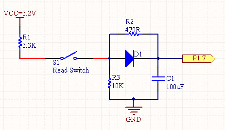
here is my circuit:

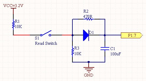
the circuit works well in normal condition but when i turn on a DC motor (3 Volt - 20mA) The LED Blinks very fast (Much faster than the Input Clock of P1.7)

The pull-down resistor (for P1.7) is Enabled. I want to Eliminate the bounce with hardware circuit to avoid unwanted interrupt.(after this step  i'm going to Use it in very low power mode)

Is it Noise that generate Interrupt ?

Is there any problem with my code?


and here is my code:


void main( void )

  // Stop watchdog timer to prevent time out reset
   WDTCTL = WDTPW + WDTHOLD;
 
  // Set up the button as interruptible
  P1DIR &= ~BIT7;
  P1REN |= BIT7;
  P1IES |= BIT7;
  P1IFG = 0;
  P1OUT &= ~BIT7;
  P1IE  |= BIT7;

  // Initialize Port J
  PJOUT = 0x00;
  PJDIR = 0xFF;

  // Set up LEDs
  P1OUT &= ~BIT0;
  P1DIR |= BIT0;
  P3OUT &= ~BIT6;
  P3DIR |= BIT6;
 

  while (1)
  {
   __bis_SR_register( LPM3_bits + GIE );
   __no_operation();
  }
}
//*.*.*.*.*.*.*.*.*.*.*.*.*.*.*.*.*.*.*.*.*.*.*.*.*.*.*.*.*.*.*.*.*.*.*.*.*.*.*.*.*.*.*.*.*.*.*.*.*.*.*.*.*.*.*.*.
// Port 1 interrupt service routine
#pragma vector=PORT1_VECTOR
__interrupt void Port_1(void)

 
  switch (__even_in_range(P1IV,16))
  {
  case  0: break;                                                      
  case  2: break;                                                       
  case  4: break;                                                          
  case  6: break;                                                           
  case  8: break;       
  case  10:break;                                        
  case  12:break;             
  case  14:break;                                                                
  case  16:              
     P1OUT ^= BIT0;  
  break; 
  }
 }


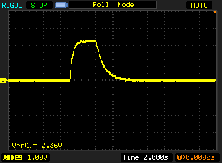
The P1.7 Pulse Image:

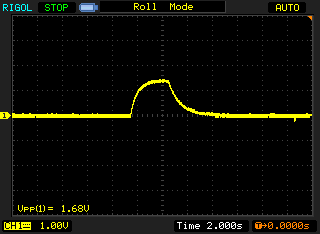
as you seen the Low to High Pulse is sharp but when the DC motor is ON The MCU Generate Unwanted Interrupt every where (not only in Low to High transition)

The DC motor Supply voltage is completely Isolated from MCU Power supply.

Thank U

and

HAPPY NEW YEAR

  • DC motors are contructed with magnets and coil, thoses motors generates magnetics field and a reed switch is activated with a magnetic field, it is possible that the noise of the motor perturbate the reed, but the magnetic noise, not the electrical one.

    Try to put the motor farther, or to build a "para-magnetic" cage with some mumetal.


    I've not read the code at that time (the debounce circuirt seems ok), so I will not comment it, try the "trick" above and come back;)

  • Thank U Argail for the Post.

    I am using the DC motor for a source of noise (to test my circuit). as i mentioned the circuit works well in normal condition.

    but it generate unwanted interrupts when the DC motor is on. ( i never have had problem with other MCU in such conditions before)

    In addition i have tested the circuit with a complete  Clear Square wave ( I have omitted the read switch ,but the problem still remains.)

    Even when i apply the square wave to the pin (with the Presence of noise) the MCU Generates Unwanted interrupts ( and I used external small pull-down resistors)


    Best  Regards

    Goodarz

  • Your debouncer has a major design flaw:

    You load teh capacitor through a 10k resistor. Yet the capacitor has another 10k in parallel to ground. This means that the maximum voltage you can load the capacitor to is 1.6V. This is in the area of the input pin hysteresis. Through the diode, the loading voltage is even reduced to (in case of a schottky) 1.4V and then the additional 470R are in row with 10k pullup filling it up to 1.56V.

    Taking 3.2V as the MSPs supply voltage, the schmitt-trigger inputs require 1.5V..2.1V as positive going voltage. The negative going voltage is in teh range of 0.75..1.65 with a guaranteed hysteresis of 0.4V. So any signal causing emall changes in the voltage will cause the inputs to trigger. If you're unlucky, your DC motor (or any other periodic distortion) may even cause the circuit to oscillate around the trigger point.

    If you lower the pullup resistor to 4.7k, you shift the whole thing up by 0.5V. Which then is in the worst-case range of the positive-going threshold and well above the negative-going threshold. 3.3k would be even better for the pullup.

  • Dear Jens-Michael Gross

    Thank U for Quick and Useful reply.

    I have changed the Debounce circuit as you said :

    I have replaced the 10K Resistor with a 3.3K one and here is the Screen shot of my pulse:

    as you see in above picture the Vp-p = 2.63

    and i have changed a little in my code :


    void main( void )
    {
      // Stop watchdog timer to prevent time out reset
       WDTCTL = WDTPW + WDTHOLD;
     
      // Set up the button as interruptible
      P1DIR &= ~BIT7;
      P1REN |= BIT7;
      P1IES &= ~BIT7;
      P1IFG = 0;
      P1OUT &= ~BIT7;
      P1IE  |= BIT7;

      // Initialize Port J
      PJOUT = 0x00;
      PJDIR = 0xFF;

      // Set up LEDs
      P1OUT &= ~BIT0;
      P1DIR |= BIT0;
      P3OUT &= ~BIT6;
      P3DIR |= BIT6;
     

      while (1)
      {
       __bis_SR_register( LPM3_bits + GIE );
       __no_operation();
      }
    }
    //*.*.*.*.*.*.*.*.*.*.*.*.*.*.*.*.*.*.*.*.*.*.*.*.*.*.*.*.*.*.*.*.*.*.*.*.*.*.*.*.*.*.*.*.*.*.*.*.*.*.*.*.*.*.*.*.
    // Port 1 interrupt service routine
    #pragma vector=PORT1_VECTOR
    __interrupt void Port_1(void)
    {
     
      switch (__even_in_range(P1IV,16))
      {
      case  0: break;                                                     
      case  2: break;                                                      
      case  4: break;                                                         
      case  6: break;                                                          
      case  8: break;      
      case  10:break;                                       
      case  12:break;            
      case  14:break;                                                               
      case  16:             
         P1OUT ^= BIT0;
         P1IFG &= ~BIT7;                          // P1.7 IFG cleared
      break;
      }
     }

    unfortunately the problem didn't solved, still the MCU generate Unwanted interrupts.

    (Even when I tight the P1.7 With a single Pull-down Resistor to GND. in presence of noise the MCU  generate Unwanted Noise)

    is there any problem with my code?

    How can I Change my code to avoid Multiple Interrupt in a single (Low to High) transition

  • Well, the signal looks much better now. :)

    Another thing I'd do: you used a 100µF capacitor. This gives you a signal rise time of half a second. This is an eternity. I'm not sure what happens on the MSP port for such a long slow rise. Normally, I'd think that after the rising edge has been detected, no more interrupts will come until a falling edge is detected. so your code should be correct. But when the 'trigger point' is reached/crossed so exteremely slow, it might be that the circuit will keep the IFG bit set.

    Personally, I never used a capacitor larger than a few 100 nF for debouncing.

    Manually clearing the IFG shouldn't be necesssary, as it is automatically cleared by reading the P1IV register. But in this case it seems to resist even manually clearing....

    What you can try is to 'disarm' the interrupt by switching it to detect the falling edge. (and when an interrupt comes detectign the fallign edge, siwtch it back to rising edge and do nothing). and then manually clear the IFG bit.

    As an alternative, you can drop the debouncing circuit completely and introduce a software debouncing delay: once you got the first rising edge interrupt, disable the port interrupt and start a timer delay. When the timer delay expires, check whether the port pin is still high (to ensure that it wasn't just s apike) and re-enable the port interrupt.
    There are several variants of this possible. With such a 'software debouncer', I was able to eliminate the need of a debouncing circuit completely, saving some bucks on the hardware.

    You should, however, check your VCC during noise. And with a much higher resolution than the above 2s/div. Maybe it's not the input signal itself that causes the trouble.

    p.s.: the __no_operation() after entering LPM is not suitable for settign a debugger breakpoint. Due to the pipelined nature of the cpu core, the breakpoint will be hit before the LPM is actually entered (yet the instruction yould be executed after leaving LPM again). Add a second NOP and put the the breakpoint there.

  • Dear Jens-Michael Thank you for the post.

    I had to use the external debounce circuit to eliminate bouce because my circuit is going to be a battry powered device ( and is going to work for 10 Years with two parallel 10Ah Battery)

    So i should avoid unwanted interrupts to avoid unwanted wake-ups.

    I have replaced my 100uF Cap. with a 330nF Cap. I think the slew rate is much better now here is the signal:

    Also I have used parallel Batteries (3.6 Volt - 8.5 Ah) for Debounce and MCU circuits  power supply.  ( the supply stability is much better than befor with a 20uV P-P ripple)

    It look likes the debounce circuits work well in rising edges but unfortunately the problem Exist in High level of signal ( the Low level is good and MCU doesn't sense any interrupts.)

    as you see in above screen shot Vmax = 2.72 volt (= Logic 1)  why the MCU Sense unwanted Interrupts ONLY in "high" level !?


    Thank you

    Goodarz


  • goodarz kashian said:
    have replaced my 100uF Cap. with a 330nF Cap.

    In an old project we had in input that was pulled-up by 1k to 12V and short-circuited to GND by a relais. THis had to be debounced. We used a 100nF capacitor in sreies with a 33Ohm resistor (to limit the unloading current of the capacitor so it won't damage the relais). The resulting signal was divided by a resistor divider before feeding it into an MSP430F1232. It worked well and we never detected and multiple interrupts.

    I think, going further low with your capacitor to 100nF would further improve the signal.

    goodarz kashian said:
    why the MCU Sense unwanted Interrupts ONLY in "high" level

    The image you provided is 500ms/div, which does not show anything about the signal at rising/falling edge. The fact that the rising and fallign edge is not a straight vertical line seems to indicate that the slew rate is still very slow.(the screes jsut shows a raw estimation of <50ms which is 5 decades slower than what the MSP can handle.

    What is the output impedance of your signal source?

    I have no clue how the edge detection works on teh MSP. The datasheets do not show any circuitry. It's a black box, so I cannot make any guess about how this effect of multiple interrupts could be caused.

    I see the problem in power consumption. There is, however, a software workaround you can use (didn't I already suggest that):

    When a port interrupt is detected, disable the port interrupt and enable a timer (may run on the VLO). When the timer expires, check the current port state (which should be debounced now), re-enable the port interrupt, deactivate the timer and act based on the port pins level.

    This way you'll get only two wakeups for each port event and you save the external debounce circuitry, which will also add to power consumption (leakage currents through cpacitor etc.) which might be more than the additional MSP consumption - especially for larger capacitors like the ones you used initially.

  • The problem finally solved after several efforts:

    i solved the problem by shielding the MCU pin and disabling input pull up resistor.

**Attention** This is a public forum