This thread has been locked.

If you have a related question, please click the "Ask a related question" button in the top right corner. The newly created question will be automatically linked to this question.

MSP430G2553: ADC input pin is not tristate

Part Number: MSP430G2553

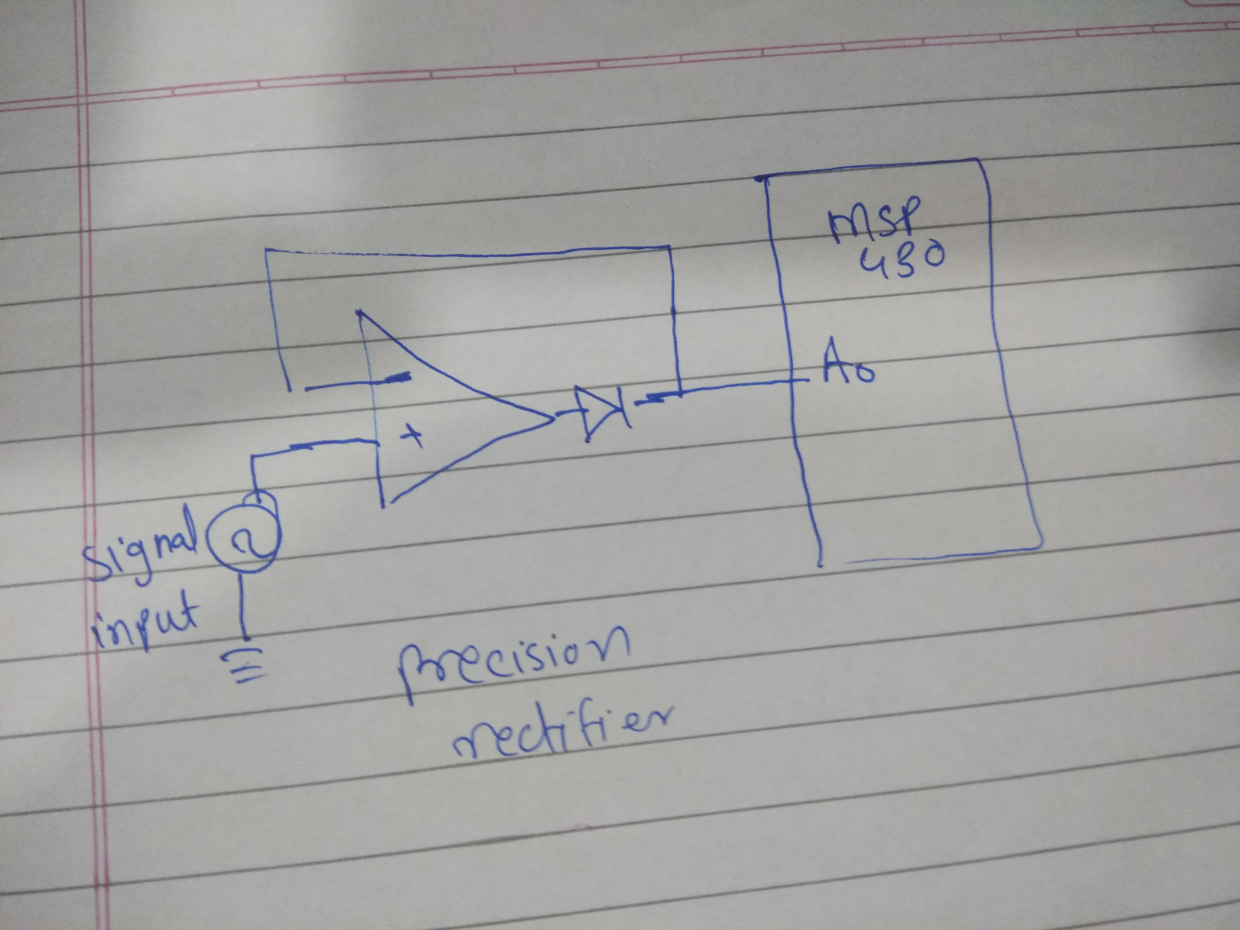
I am using MSP430G2553 to sample the analog input and process it further. When I checked voltage at ADC input pin A0 it was arround 1.4 V  even when input was not connected. Then I tried to pull down it externally then it fall to 1.1 V  instead of 0 V. I need tristate input of ADC as I am giving input from precision rectifer ,due to this I was not able to detect input level less than 1.4 V.  Here is its code.

#include <msp430g2553.h>
int PWM(int a);
int main(void) {
float err = 0,ref = 122, Vadc = 0, Kp  = 1, Ki = 0.4, P = 0, I = 0, PImax = 1000, PI = 0;

    WDTCTL = WDTPW + WDTHOLD;

            ADC10CTL0 = SREF_1 + REFON + REF2_5V + ADC10ON+ MSC;
            ADC10CTL1 = CONSEQ_2; //repeated single conversion
            ADC10AE0 = INCH_0;
            ADC10CTL0 |= ENC + ADC10SC;
            Vadc = ADC10MEM;


                while(1)
                {
                    Vadc = ADC10MEM;
                    err = ref - Vadc;
                    P = Kp * err;


                    if (PI + Ki * err < PImax)
                        I = I + Ki * err;

                    PI = P + I;

                    if(PI > PImax)
                        PI = PImax;
                   PWM(PI);
                }

            }

     int  PWM(int a)   {
            P1DIR |= BIT2;
            P1SEL |= BIT2;
            TA0CCR0 = 1000; //Set the period in the Timer A0 Capture/Compare 0 register to 1000 us.
            TA0CCTL1 = OUTMOD_7;
            TA0CCR1 = a; //The period in microseconds that the power is ON. It's half the time, which translates to a 50% duty cycle.
            TA0CTL = TASSEL_2 + MC_1; //TASSEL_2 selects SMCLK as the clock source, and MC_1 tells it to count up to the value in TA0CCR0.
     return 0;
}

  • Are you using a Launchpad? On the Launchpad (each of them) P1.0 is connected to an LED. Just remove the jumper, or maybe use, e.g. A3 A4 instead.

    >           ADC10AE0 = INCH_0;

     INCH_0 == 0, so this doesn't do much. Try:

    >           ADC10AE0 = BIT0;     // Make A0 (P1.0) an analog input pin 

    [Edit: I just remembered A3 (P1.3) is a pushbutton. I think A4 (P1.4) is unencumbered, but check anyway.]

  • I tried by removing jumper but problem still persists. Also tried with A1 - A6 ports but issue didn't resolve. 

    For bits other than A0, ADC is not giving correct results. It is showing value betwen 0x267 to 0x287 when input varied from 0 to 2.5V

  • > For bits other than A0

    Does this mean that A0 is producing correct results now?

    > Also tried with A1 - A6 ports

    How (exactly) did you try the other ports? Did you set both INCH and the relevant AE0 bit?

    P1.1-2 are used by the USB-UART through the RXD/TXD jumpers on the "bridge" header (J101). P1.3 is connected to a pushbutton, which (depending on which Launchpad you have) may or may not have a pullup resistor connected.

    What is your input source? SHT=0 is pretty short if your source isn't fairly low impedance.

  • Does this mean that A0 is producing correct results now?

    A0 never produced the wrong result.but the problem of pin voltage around 1.5 V still presents with channel A0 after removal of jumper, due to this when input is given through precision rectifer it is not sampling the input when it is less than 1.5 V because precision rectifier will not work when voltage at it's output terminal greater than input(I have attached the interfacing diagram of signal souce with ADC through precision rectifier). Therefore that pin(ADC input) must be tristated in my application.

     I tried with A4 channel and set the INCH_4 and AE0 bit 4 but it not showing correct result, but there voltage around 1.5V  at input pin even if no input source is connected. here is it's code

    #include <msp430g2553.h>
    int PWM(int a);
    int main(void) {
    float err = 0,ref = 600, Vadc = 0, Kp  = 1, Ki = 0.4, P = 0, I = 0, PImax = 1000, PI = 0;

        WDTCTL = WDTPW + WDTHOLD;

                ADC10CTL0 = SREF_1 + REFON + REF2_5V + ADC10ON+ MSC;
                ADC10CTL1 = CONSEQ_2 + INCH_4; //repeated single conversion
                ADC10AE0 = BIT4;     // Make A4 (P1.4) an analog input pin
                ADC10CTL0 |= ENC + ADC10SC;
                Vadc = ADC10MEM;

                //_bis_SR_register(GIE);


                    while(1)
                    {

                        Vadc = ADC10MEM;
                        err = ref - Vadc;
                        P = Kp * err;


                        if (PI + Ki * err < PImax)
                            I = I + Ki * err;

                        PI = P + I;

                        if(PI > PImax)
                            PI = PImax;
                        if(PI < 0)
                            PI = 0;
                       PWM(PI);
                    }

                }

         int  PWM(int a)   {
                P1DIR |= BIT2;
                P1SEL |= BIT2;
                TA0CCR0 = 1000; //Set the period in the Timer A0 Capture/Compare 0 register to 1000 us.
                TA0CCTL1 = OUTMOD_7;
                TA0CCR1 = a; //set duty cycle according to PI output
                TA0CTL = TASSEL_2 + MC_1; //TASSEL_2 selects SMCLK as the clock source, and MC_1 tells it to count up to the value in TA0CCR0.
         return 0;
    }

    This waveform shows voltage at A4 pin as soon as it is configured as input channel.

  • When I run this code on a G2 Launchpad (Rev 1.5) and connect P1.4 to GND/VCC I get 0/0x3FF respectively. When not connected, it does seem to settle around 1.5V but I can vary it +/-0.4V by touching the pin with my finger. This is more or less the way I expect it to behave.

    I'm not sure I understand the effect of the rectifier, but I'm not a EE.

  • The output of the rectifier should be very low impedance and be able to drive the MCU input with no issue.

  • Because of that diode your signal source can only source current. You need something on the ADC side of that diode to sink current or it will just float around. A 1K resistor should do the trick. Although it could vary depending on sampling time.

  • A moderate load resistor should do the trick. Generally, you follow a precision rectifier with some sort of peak detector.

  • A 1K resistor should do the trick.

    I tried that too but did not work in my so I added buffer stage in between MCU and rectifier. Now it is working properly

**Attention** This is a public forum