This thread has been locked.

If you have a related question, please click the "Ask a related question" button in the top right corner. The newly created question will be automatically linked to this question.

CCS/MSP430FR5962: IPE (Intellectual Property Encapsulation) code and address update

Part Number: MSP430FR5962
Other Parts Discussed in Thread: MSP430FR5969

Tool/software: Code Composer Studio

Hello,

Here I designed two different project(bootloader and main projects) on different memory segments.

bootloader location from 0x004000 to 0x008000.
main program from 0x008000 to 0x01C000.

They all arranged from the "lnk_msp430fr5962.cmd" file

At first, my bootloader project was flashed to MCU from CCS (v9.2.0.00013) via MSP_FET debugger. Then, main program was downloaded via UART. After that, I have two separate program in my MCU and I can switch one to another without any problem. Switching issue between programs happens with changing interrupt vectors and signatures before BOR_reset. It works very well until there.

Main program has IPE and data. If location of ipe area is different in new version of the main program, it doesnt work. 

The Problem is That:

Ipe segments values (MPUIPSEGB2) are returning first main programs' values. I am trying to change but after RESET, segment values are returns their first values.

New program already comes with its own IpeStruct values and the other codes. But new ipe area is not set in its segment values. 

How I am able to manually change IPE area start address? Is there any special method?

Thank you for your patience and helps...

  • Hi 

    I saw your boot code is from 0x4000 to 0x8000 that is about 16kb. Have you saw the demo code from TI like this one link . For this demo the boot code just have no more than 4kb that will save some memory for you. What's more, it has the code to change IPE area code in project like MSP430FR5969. In this demo, it configure the MPU in boot code once to protect boot code area not allow to be changed. Will you reconfigure the MPU in the application code? And why?

    Do you want to keep two different application codes in device at the same time? In our demo code, we just keep one application code in the device.

    Best regards

    Gary

  • Hi,

    As you said, I have two different application code in one chip. I think, size of application is not much important if this is 16kb or 4kb. This is just an application which has access to write data inside of chip. Assume, there is two applications are named 'A' and 'B'. Vectors and signatures are stored in a special area for both A and B applications.

    Switching from A to B:

    1- Disable global interrupts
    2- Write B vectors and signatures from 0xFF80 to 0xFFFF (if neccessary disable MPU with code before that)
    3- Bor Reset. 

    After that, application B starts run with its own MPU configuration which is set from CCS before building project.

    There is no MPU code in main() function. MPU codes are just running with "__mpu_init()" which is under "_c_int00_template()" at boot.c .
    I know where is MPU init codes but I am not sure where is IPE configurations are done before main().

    Is this related with TLV area in fram?  I am not able to make changes in this area but,  I see some changes in TLV, after downloading any other application via MSP_Fet debugger. I asked that because 0x1AEE address has a value of ipe_struct address.


    Thank you...

  • Hi 

    Before you change vectors and signatures from 0xFF80 to 0xFFFF you must disable the IPE

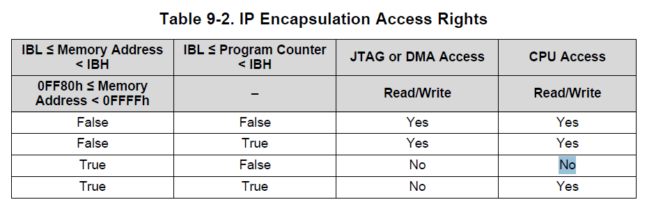
    To configure the segments, a lower (IBL) border and a higher (IBH) border are positioned by control register bits MPUIPSEGB1[15:0] and MPUIPSEGB2[15:0], respectively, in the MPUIPSEGBx register. We do have a appnote about how to use the IPE http://www.ti.com/lit/an/slaa685/slaa685.pdf 

    You can also refer to this thread https://e2e.ti.com/support/microcontrollers/msp430/f/166/p/428782/1532612#1532612

         There is no MPU code in main() function. 

    For this, which project do you mean? Your project or our demo?

         0x1AEE address has a value of ipe_struct address

    where you get that value?

  • Hi, 

    Gary Gao said:
    Before you change vectors and signatures from 0xFF80 to 0xFFFF you must disable the IPE

    Absolutely, IPE is disabled just before start downloading. 

    Debug mode in CCS, Memory Browser shows just 0x3FFF for IPE area. After unlock and disable function, I am able to see real data in this area. Then, I am changing  MPUIPSEGBx registers, ipe_struct_pointer and ne ipe_structure with the code below. Finally, I am locking and enabling MPU and IPE features.
    After BOR reset, MPUIPSEGBx return its previous values

    unsigned int * ipe_start = (unsigned int *)0x8000;
    unsigned int * ipe_struct_ptr = (unsigned int *)0xFF8A;

    MPUCTL0 = (MPUPW + (MPUCTL0 & 0x00FF)) & ~MPULOCK; // unlock MPU

    MPUIPC0 &= ~(MPUIPLOCK + MPUIPENA);  // IPE unlock and disable
    MPUIPSEGB2 = 0x0A00;                                 // new ipe end 0xA000 >> 4
    MPUIPSEGB1 = 0x0800;                                 // new ipe start 0x8000 >> 4

    // create ipe structure 
    *ipe_start = 0x0040;                 // IPE enable
    ipe_start++;
    *ipe_start = MPUIPSEGB2;     // IPE end
    ipe_start++;
    *ipe_start = MPUIPSEGB1;     // IPE start
    ipe_start++;
    *ipe_start = ~((0x0040 ^ MPUIPSEGB2) ^ MPUIPSEGB1);    // IPE structure Checksum

    *ipe_struct_ptr = MPUIPSEGB1;                                              // IPE structure Pointer
    MPUIPC0 |= MPUIPLOCK + MPUIPENA;                                // Lock and enable IPE
    MPUCTL0 = MPUPW + (MPUCTL0 & 0x00FF) + MPULOCK; // Lock MPU

    Is there anything wrong?

    Thank you..

  • After the BOR all the registers will be changed to its default value you need to reconfigure it in the initialization code.

  • You are right, Reset Vector indicates beginning of the initialization code. It must set the configuration at the beginning.

    Applications have different ipe settings. Thats why, after switching application, I must see the difference in MPUIPxxx registers, Because, I am also changing reset vector to indicate other application's init code.

    According to  Memory Browser in CCS, I see that if ipe is configured once, this is not able to change ipe configuration permanently. 

    Thank you...

  • user6234665 said:
    According to  Memory Browser in CCS, I see that if ipe is configured once, this is not able to change ipe configuration permanently.

    Does  that mean you may have three different IPE configuration in boot code, application code A and application code B. For first time you down load the boot code and configured the IPE that is by default configuration. Do you need this default IPE configuration? If not you can disable it and just configure the IPE in your application code.  To disable the default configuration you can just don't select the option like this

  • At first, I download app A from CCS with MSP_Fet. Then, application B is downloaded by app A via UART. After that, Both A and B are on the chip.

    I can switch between A and B. After switching, every configuration changes (MPU config also changes) except IPE configurations.

    For applicatin A, IPE disabled.
    For applicatin B, IPE enabled (segment 1 is not manually spesified).

    I change the IPE configuration for program B in CCS and build application again.(new version of B)

    While app A is running, I am also able to erase app B. Then, I download  newer version fo B via UART. Switched to B (with BOR reset).
    After all, I still see IPE config belongs to previous version of B. This is the exact point where I am crash.

  • Hi 

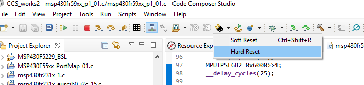
    I have set up the hardware and reproduce this issue with press the reset button to generate the BOR in debug mode. But when I use the hardware reset in the CCS this problem is gone just like below

    How do you generate the BOR?

  • Hi

    I got one reason for my situation is that in debug mode I use the the SBW interface that will change the RST pin to communication mode not the reset button so press the reset button will not work. I have try the 4-wire JTAG that will works well without any problem.

    Best regards

    Gary

  • Hi,

    Here generating bor reset with code:

    PMMCTL0 = PMMPW | PMMSWBOR

    I am not sure this situation is related with JTAG or SBW. Because, I am also controlling ipe registers with UART commands which is included in application. 

    If debug mode failed anyway, you can reconnect without erasing or changing anything. You can use Red Rectangled settings to use debug to reconnect while application is still running. 

    Please flash application with CCS and generate BOR or hard reset. After that you will see IPE values from the related location:

    You can try to shift ipe start and end add. in the code. After that please check new ipe area to see if this is really changed. Then generate a BOR. After that re-check ipe setting if still indicates new area.

    You will see ipe registers will show you pre-configured address.

    Thank you..

  • Hi 

    First I want to clear that you can just to reconfigure the IPE registers after BOR. I have test the it with PMMCTL0 = PMMPW | PMMSWBOR; and it work well. My test hardware is MSP430FR5969 Launchpad and the test code is attached 

    /* --COPYRIGHT--,BSD_EX
     * Copyright (c) 2012, Texas Instruments Incorporated
     * All rights reserved.
     *
     * Redistribution and use in source and binary forms, with or without
     * modification, are permitted provided that the following conditions
     * are met:
     *
     * *  Redistributions of source code must retain the above copyright
     *    notice, this list of conditions and the following disclaimer.
     *
     * *  Redistributions in binary form must reproduce the above copyright
     *    notice, this list of conditions and the following disclaimer in the
     *    documentation and/or other materials provided with the distribution.
     *
     * *  Neither the name of Texas Instruments Incorporated nor the names of
     *    its contributors may be used to endorse or promote products derived
     *    from this software without specific prior written permission.
     *
     * THIS SOFTWARE IS PROVIDED BY THE COPYRIGHT HOLDERS AND CONTRIBUTORS "AS IS"
     * AND ANY EXPRESS OR IMPLIED WARRANTIES, INCLUDING, BUT NOT LIMITED TO,
     * THE IMPLIED WARRANTIES OF MERCHANTABILITY AND FITNESS FOR A PARTICULAR
     * PURPOSE ARE DISCLAIMED. IN NO EVENT SHALL THE COPYRIGHT OWNER OR
     * CONTRIBUTORS BE LIABLE FOR ANY DIRECT, INDIRECT, INCIDENTAL, SPECIAL,
     * EXEMPLARY, OR CONSEQUENTIAL DAMAGES (INCLUDING, BUT NOT LIMITED TO,
     * PROCUREMENT OF SUBSTITUTE GOODS OR SERVICES; LOSS OF USE, DATA, OR PROFITS;
     * OR BUSINESS INTERRUPTION) HOWEVER CAUSED AND ON ANY THEORY OF LIABILITY,
     * WHETHER IN CONTRACT, STRICT LIABILITY, OR TORT (INCLUDING NEGLIGENCE OR
     * OTHERWISE) ARISING IN ANY WAY OUT OF THE USE OF THIS SOFTWARE,
     * EVEN IF ADVISED OF THE POSSIBILITY OF SUCH DAMAGE.
     *
     *******************************************************************************
     *
     *                       MSP430 CODE EXAMPLE DISCLAIMER
     *
     * MSP430 code examples are self-contained low-level programs that typically
     * demonstrate a single peripheral function or device feature in a highly
     * concise manner. For this the code may rely on the device's power-on default
     * register values and settings such as the clock configuration and care must
     * be taken when combining code from several examples to avoid potential side
     * effects. Also see www.ti.com/grace for a GUI- and www.ti.com/msp430ware
     * for an API functional library-approach to peripheral configuration.
     *
     * --/COPYRIGHT--*/
    //******************************************************************************
    //  MSP430FR59xx Demo - Software Poll P1.4, Set P1.0 if P1.4 = 1
    //
    //  Description: Poll P1.4 in a loop, if hi P1.0 is set, if low, P1.0 reset.
    //  ACLK = n/a, MCLK = SMCLK = default DCO
    //
    //              MSP430FR5969
    //            -----------------
    //        /|\|              XIN|-
    //         | |                 |
    //         --|RST          XOUT|-
    //     /|\   |                 |
    //      --o--|P1.4         P1.0|-->LED
    //     \|/
    //
    //   T. Witt
    //   Texas Instruments Inc.
    //   November 2011
    //   Built with IAR Embedded Workbench V5.30 & Code Composer Studio V5.5
    //******************************************************************************
    #include <msp430.h>
    
    #pragma PERSISTENT(flag)
    unsigned int flag = 0;
    
    int main(void)
    {
      char rest_flag=0;
      WDTCTL = WDTPW | WDTHOLD;                 // Stop watchdog timer
    
    
      // Configure GPIO
      P1DIR |= BIT0;                            // Set P1.0 to output direction
      P4DIR |= BIT6;
      P4OUT &= ~BIT6;
      P1OUT &= ~BIT0;
      // Disable the GPIO power-on default high-impedance mode to activate
      // previously configured port settings
      PM5CTL0 &= ~LOCKLPM5;
     // __bis_SR_register(GIE);
    
      if(flag)
      {
          P4OUT |= BIT6;                         // P1.0 = toggle
          __delay_cycles(1000000);
          P4OUT &= ~BIT6;
          __delay_cycles(1000000);
          MPUCTL0 = MPUPW;
          MPUIPC0=0;
          __delay_cycles(25);
          MPUIPSEGB1=0x5000>>4;
          __delay_cycles(25);
          MPUIPSEGB2=0x6000>>4;
          __delay_cycles(25);
    
          if(MPUIPSEGB1==0x500)
          {
              P4OUT |= BIT6;                         // P1.0 = toggle
              __delay_cycles(500000);
              P4OUT &= ~BIT6;
              __delay_cycles(500000);
              rest_flag=1;
          }
          MPUIPC0=MPUIPLOCK|MPUIPENA;
          flag=0;
      }else
      {
          P1OUT |= BIT0;
          __delay_cycles(1000000);                           // P1.0 = toggle
          P1OUT &= ~BIT0;
          __delay_cycles(1000000);
          MPUCTL0 = MPUPW;
          MPUIPC0=0;
          __delay_cycles(25);
          MPUIPSEGB1=0x6000>>4;
          __delay_cycles(25);
          MPUIPSEGB2=0x7000>>4;
          __delay_cycles(25);
    
          if(MPUIPSEGB1==0x600)
          {
              P1OUT |= BIT0;                         // P1.0 = toggle
              __delay_cycles(500000);
              P1OUT &= ~BIT0;
              __delay_cycles(500000);
              rest_flag=1;
          }
    
          MPUIPC0=MPUIPLOCK|MPUIPENA;
    
          flag=1;
          __delay_cycles(25);
      }
    
      while (1)                                 // Test P1.4
      {
        __delay_cycles(2000000);
        if(rest_flag)
        PMMCTL0 = PMMPW | PMMSWBOR;
      }
    }
    

  • Hi,

    In the below, I created an example project which is similar to yours. Four led connected for debug purpose only. 

    There is four different case in application. Cases are indicated by Leds. After downloading application, "Case 4" runs just once. After that, application runs just "Case 1" after each reset.

    IPE_test_project.rar

  • Some problem in your code

    1. After BOR the IPE registers will changed to default value. I just test with MSP430FR5969, the value of MPUIPSEGB1 is 0x480 after BOR.That means after BOR MPUIPSEGB1 will always be the default value.

    2. Why you put the your code in the while(1) loop? You can just configure the IPE register only once at once running.

    Please refer to my codes, you can see I use a variable "flag" that defined in the FRAM memory that means when BOR or power off the flag can keep the value that when before BOR.

    What's more you can see, I have the code "if(MPUIPSEGB1==0x500)" to check if I have change IPE register successfully and I have the results is it work well!

  • Hi,

    I want to be more clear with your code. I added 1 line at the beginning of main and, if condititon just after locking ipe again. You can find my edit: 

    /* --COPYRIGHT--,BSD_EX
     * Copyright (c) 2012, Texas Instruments Incorporated
     * All rights reserved.
     *
     * Redistribution and use in source and binary forms, with or without
     * modification, are permitted provided that the following conditions
     * are met:
     *
     * *  Redistributions of source code must retain the above copyright
     *    notice, this list of conditions and the following disclaimer.
     *
     * *  Redistributions in binary form must reproduce the above copyright
     *    notice, this list of conditions and the following disclaimer in the
     *    documentation and/or other materials provided with the distribution.
     *
     * *  Neither the name of Texas Instruments Incorporated nor the names of
     *    its contributors may be used to endorse or promote products derived
     *    from this software without specific prior written permission.
     *
     * THIS SOFTWARE IS PROVIDED BY THE COPYRIGHT HOLDERS AND CONTRIBUTORS "AS IS"
     * AND ANY EXPRESS OR IMPLIED WARRANTIES, INCLUDING, BUT NOT LIMITED TO,
     * THE IMPLIED WARRANTIES OF MERCHANTABILITY AND FITNESS FOR A PARTICULAR
     * PURPOSE ARE DISCLAIMED. IN NO EVENT SHALL THE COPYRIGHT OWNER OR
     * CONTRIBUTORS BE LIABLE FOR ANY DIRECT, INDIRECT, INCIDENTAL, SPECIAL,
     * EXEMPLARY, OR CONSEQUENTIAL DAMAGES (INCLUDING, BUT NOT LIMITED TO,
     * PROCUREMENT OF SUBSTITUTE GOODS OR SERVICES; LOSS OF USE, DATA, OR PROFITS;
     * OR BUSINESS INTERRUPTION) HOWEVER CAUSED AND ON ANY THEORY OF LIABILITY,
     * WHETHER IN CONTRACT, STRICT LIABILITY, OR TORT (INCLUDING NEGLIGENCE OR
     * OTHERWISE) ARISING IN ANY WAY OUT OF THE USE OF THIS SOFTWARE,
     * EVEN IF ADVISED OF THE POSSIBILITY OF SUCH DAMAGE.
     *
     *******************************************************************************
     *
     *                       MSP430 CODE EXAMPLE DISCLAIMER
     *
     * MSP430 code examples are self-contained low-level programs that typically
     * demonstrate a single peripheral function or device feature in a highly
     * concise manner. For this the code may rely on the device's power-on default
     * register values and settings such as the clock configuration and care must
     * be taken when combining code from several examples to avoid potential side
     * effects. Also see www.ti.com/grace for a GUI- and www.ti.com/msp430ware
     * for an API functional library-approach to peripheral configuration.
     *
     * --/COPYRIGHT--*/
    //******************************************************************************
    //  MSP430FR59xx Demo - Software Poll P1.4, Set P1.0 if P1.4 = 1
    //
    //  Description: Poll P1.4 in a loop, if hi P1.0 is set, if low, P1.0 reset.
    //  ACLK = n/a, MCLK = SMCLK = default DCO
    //
    //              MSP430FR5969
    //            -----------------
    //        /|\|              XIN|-
    //         | |                 |
    //         --|RST          XOUT|-
    //     /|\   |                 |
    //      --o--|P1.4         P1.0|-->LED
    //     \|/
    //
    //   T. Witt
    //   Texas Instruments Inc.
    //   November 2011
    //   Built with IAR Embedded Workbench V5.30 & Code Composer Studio V5.5
    //******************************************************************************
    #include <msp430.h>
    
    #pragma PERSISTENT(flag)
    unsigned int flag = 0;
    
    int main(void)
    {
    //////////////////////////////  EDIT
        //get default ipe start addr in the beginning
        unsigned long default_ipe_start_value = MPUIPSEGB1;
    /////////////////////////////
    
      char rest_flag=0;
      WDTCTL = WDTPW | WDTHOLD;                 // Stop watchdog timer
    
    
      // Configure GPIO
      P1DIR |= BIT0;                            // Set P1.0 to output direction
      P4DIR |= BIT6;
      P4OUT &= ~BIT6;
      P1OUT &= ~BIT0;
      // Disable the GPIO power-on default high-impedance mode to activate
      // previously configured port settings
      PM5CTL0 &= ~LOCKLPM5;
     // __bis_SR_register(GIE);
    
      if(flag)
      {
          P4OUT |= BIT6;                         // P1.0 = toggle
          __delay_cycles(1000000);
          P4OUT &= ~BIT6;
          __delay_cycles(1000000);
          MPUCTL0 = MPUPW;
          MPUIPC0=0;
          __delay_cycles(25);
          MPUIPSEGB1=0x5000>>4;
          __delay_cycles(25);
          MPUIPSEGB2=0x6000>>4;
          __delay_cycles(25);
    
          if(MPUIPSEGB1==0x500)
          {
              P4OUT |= BIT6;                         // P1.0 = toggle
              __delay_cycles(500000);
              P4OUT &= ~BIT6;
              __delay_cycles(500000);
              rest_flag=1;
          }
          MPUIPC0=MPUIPLOCK|MPUIPENA;
          flag=0;
      }
      else
      {
          P1OUT |= BIT0;
          __delay_cycles(1000000);                           // P1.0 = toggle
          P1OUT &= ~BIT0;
          __delay_cycles(1000000);
          MPUCTL0 = MPUPW;
          MPUIPC0=0;
          __delay_cycles(25);
          MPUIPSEGB1=0x6000>>4;
          __delay_cycles(25);
          MPUIPSEGB2=0x7000>>4;
          __delay_cycles(25);
    
          if(MPUIPSEGB1==0x600)
          {
              P1OUT |= BIT0;                         // P1.0 = toggle
              __delay_cycles(500000);
              P1OUT &= ~BIT0;
              __delay_cycles(500000);
              rest_flag=1;
          }
    
          MPUIPC0=MPUIPLOCK|MPUIPENA;
    
          flag=1;
          __delay_cycles(25);
      }
    ////////////////////////////  EDIT
      if(default_ipe_start_value != 0)  // dont run with first run after download application
      {
          // shift 4 bit left to get real register address
          unsigned char * ptr_default_ipe_start = (unsigned char *)(default_ipe_start_value << 4);
          // This is not an ipe ipe addr. anymore. So, we must be able to change that register with any value
          *ptr_default_ipe_start = 0x01;
      }
    ////////////////////////////
    
    //  while (1)                                 // Test P1.4
    //  {
        __delay_cycles(2000000);
        if(rest_flag)
        PMMCTL0 = PMMPW | PMMSWBOR;
    //  }
    }
    

    After changing ipe settings (also ipe start address), I must be able to write anything to default ipe start address. Because, device have new ipe area and settings. Something goes wrong with this edit. Can you please have a look.

  • Hi 

    We don't need to care the default value because after BOR the IPE registers changed to default value and it is disabled at the same time. I know what's mean, you just want to know if we can write the memory that address at the area of last time IPE protected. I have changed  the code, you can see at first time, I configure the 0x6000~0x7000 to IPE protected area, after that I generate a BOR and change the IPE protected area to 0x5000~0x6000  and I can change the variable at 0x6500 successfully then I generate a BOR and change the IPE  protected area to 0x6000~0x7000  and I can change the variable at 0x5500 successfully then hen I generate a BOR and change the IPE.........

    /* --COPYRIGHT--,BSD_EX
     * Copyright (c) 2012, Texas Instruments Incorporated
     * All rights reserved.
     *
     * Redistribution and use in source and binary forms, with or without
     * modification, are permitted provided that the following conditions
     * are met:
     *
     * *  Redistributions of source code must retain the above copyright
     *    notice, this list of conditions and the following disclaimer.
     *
     * *  Redistributions in binary form must reproduce the above copyright
     *    notice, this list of conditions and the following disclaimer in the
     *    documentation and/or other materials provided with the distribution.
     *
     * *  Neither the name of Texas Instruments Incorporated nor the names of
     *    its contributors may be used to endorse or promote products derived
     *    from this software without specific prior written permission.
     *
     * THIS SOFTWARE IS PROVIDED BY THE COPYRIGHT HOLDERS AND CONTRIBUTORS "AS IS"
     * AND ANY EXPRESS OR IMPLIED WARRANTIES, INCLUDING, BUT NOT LIMITED TO,
     * THE IMPLIED WARRANTIES OF MERCHANTABILITY AND FITNESS FOR A PARTICULAR
     * PURPOSE ARE DISCLAIMED. IN NO EVENT SHALL THE COPYRIGHT OWNER OR
     * CONTRIBUTORS BE LIABLE FOR ANY DIRECT, INDIRECT, INCIDENTAL, SPECIAL,
     * EXEMPLARY, OR CONSEQUENTIAL DAMAGES (INCLUDING, BUT NOT LIMITED TO,
     * PROCUREMENT OF SUBSTITUTE GOODS OR SERVICES; LOSS OF USE, DATA, OR PROFITS;
     * OR BUSINESS INTERRUPTION) HOWEVER CAUSED AND ON ANY THEORY OF LIABILITY,
     * WHETHER IN CONTRACT, STRICT LIABILITY, OR TORT (INCLUDING NEGLIGENCE OR
     * OTHERWISE) ARISING IN ANY WAY OUT OF THE USE OF THIS SOFTWARE,
     * EVEN IF ADVISED OF THE POSSIBILITY OF SUCH DAMAGE.
     *
     *******************************************************************************
     *
     *                       MSP430 CODE EXAMPLE DISCLAIMER
     *
     * MSP430 code examples are self-contained low-level programs that typically
     * demonstrate a single peripheral function or device feature in a highly
     * concise manner. For this the code may rely on the device's power-on default
     * register values and settings such as the clock configuration and care must
     * be taken when combining code from several examples to avoid potential side
     * effects. Also see www.ti.com/grace for a GUI- and www.ti.com/msp430ware
     * for an API functional library-approach to peripheral configuration.
     *
     * --/COPYRIGHT--*/
    //******************************************************************************
    //  MSP430FR59xx Demo - Software Poll P1.4, Set P1.0 if P1.4 = 1
    //
    //  Description: Poll P1.4 in a loop, if hi P1.0 is set, if low, P1.0 reset.
    //  ACLK = n/a, MCLK = SMCLK = default DCO
    //
    //              MSP430FR5969
    //            -----------------
    //        /|\|              XIN|-
    //         | |                 |
    //         --|RST          XOUT|-
    //           |                 |
    //           |             P1.0|-->LED
    //
    //
    //   T. Witt
    //   Texas Instruments Inc.
    //   November 2011
    //   Built with IAR Embedded Workbench V5.30 & Code Composer Studio V5.5
    //******************************************************************************
    #include <msp430.h>
    
    #pragma PERSISTENT(flag)
    unsigned int flag = 0;   //defined in the FRAM memory, it will keep the value after BOR
    
    #define T_ADDRESS1 0x5500
    #define T_ADDRESS2 0x6500
    
    int main(void)
    {
      char rest_flag=0;      //Indicate if the IPE registers changed successfully
      WDTCTL = WDTPW | WDTHOLD;                 // Stop watchdog timer
    
    
      // Configure GPIO
      P1DIR |= BIT0;                            // Set P1.0 to output direction
      P4DIR |= BIT6;
      P4OUT &= ~BIT6;
      P1OUT &= ~BIT0;
      // Disable the GPIO power-on default high-impedance mode to activate
      // previously configured port settings
      PM5CTL0 &= ~LOCKLPM5;
     // __bis_SR_register(GIE);
      *(unsigned char *) T_ADDRESS1 = 0;
      *(unsigned char *) T_ADDRESS2 = 0;
    
      if(flag)
      {
          P4OUT |= BIT6;                         // P1.0 = toggle
          __delay_cycles(1000000);
          P4OUT &= ~BIT6;
          __delay_cycles(1000000);
          MPUCTL0 = MPUPW;
          MPUIPC0=0;
          __delay_cycles(25);
          MPUIPSEGB1=0x5000>>4;
          __delay_cycles(25);
          MPUIPSEGB2=0x6000>>4;
          __delay_cycles(25);
    
          if(MPUIPSEGB1==0x500)     // if the IPE registers changed successfully: 1 YES 0 NO
          {
              P4OUT |= BIT6;                         // P1.0 = toggle
              __delay_cycles(500000);
              P4OUT &= ~BIT6;
              __delay_cycles(500000);
              rest_flag=1;
          }
          MPUIPC0=MPUIPLOCK|MPUIPENA;
          flag=0;
          __delay_cycles(25);
          *(unsigned char *) T_ADDRESS2 = 0x55; //We can change the data in 0x6500
          __delay_cycles(25);
      }else
      {
          P1OUT |= BIT0;
          __delay_cycles(1000000);                           // P1.0 = toggle
          P1OUT &= ~BIT0;
          __delay_cycles(1000000);
          MPUCTL0 = MPUPW;
          MPUIPC0=0;
          __delay_cycles(25);
          MPUIPSEGB1=0x6000>>4;
          __delay_cycles(25);
          MPUIPSEGB2=0x7000>>4;
          __delay_cycles(25);
    
          if(MPUIPSEGB1==0x600)  // if the IPE registers changed successfully: 1 YES 0 NO
          {
              P1OUT |= BIT0;                         // P1.0 = toggle
              __delay_cycles(500000);
              P1OUT &= ~BIT0;
              __delay_cycles(500000);
              rest_flag=1;
          }
    
          MPUIPC0=MPUIPLOCK|MPUIPENA;
    
          flag=1;
          __delay_cycles(25);
          *(unsigned char *) T_ADDRESS1 = 0x66;//We can change the data in 0x5500
          __delay_cycles(25);
      }
    
      while (1)                                 // Test P1.4
      {
        __delay_cycles(2000000);
        if(rest_flag)
        PMMCTL0 = PMMPW | PMMSWBOR;
      }
    }
    

  • Hello from the new year :)

    Yes, this is a solution to change ipe setting at the beginning of main but, I am looking for if there is a better solution.

    After updating application B via application A (bootloader app.), application B runs with new MPU setting, new Jtag password etc. without any new code at the beginning.  Except IPE settings, everything works same like that I flash program via CCS, 

    I want to know what is the reason of that. Can default IPE settings be only changable via MSP_Fet or any debugger?

    Thank you,
    Best regards...

  • Hi 

    I have mentioned it before that we can just to reconfigure the IPE registers after BOR. You can refer to the user's guide section 9.5

    Best regards

    Gary

**Attention** This is a public forum