This thread has been locked.

If you have a related question, please click the "Ask a related question" button in the top right corner. The newly created question will be automatically linked to this question.

CCS/MSP430FR2512: MSP430: UART sample code

Part Number: MSP430FR2512
Other Parts Discussed in Thread: EVM430-CAPMINI, MSP430FR2422

Tool/software: Code Composer Studio

hi, 

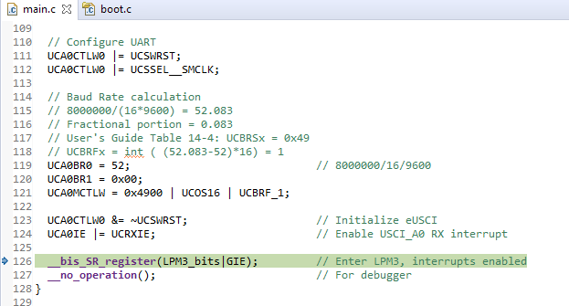
does anyone have UART sample codes for MSP430FR2512?

i've tried using MSP430FR2xxx_euscia0_uart_01.c & MSP430FR2xxx_euscia0_uart_03.c &MSP430FR2xxx_euscia0_uart_06.c but nothing seems to work. i cant see any data coming into Putty. any help will be very much appreciated. 

thank you. 

  • Are you using the CAPMINI board?

    ----------------

    If so:

    1) Are you attaching your serial wires directly to J3, rather than using the USB (via the F5510)?

    2)  The uart_01 example (in Resource Explorer) uses P1.4/5 for the UART, but the "alternate" pins (P2.0/1) are the ones connected to J3. To use those:

    2a) Set SYSCFG3:USCIARMP to use the "alternate" pins [Ref data sheet (SLASEE4C) Table 6-11]

    2b) Change:

    > P1SEL0 |= BIT4 | BIT5; 

    to 

    > P2SEL0 |= BIT0 | BIT1; // P2.0/1 as UCA0RXD/TXD per data sheet Table 6-16

    ----------------

    If you're not using the CAPMINI, you may find the USCI Troubleshooting Guide (SLAA734A) useful.

  • hi, 

    i tried to edit based on MSP430FR2xxx_euscia0_uart_01.c example, change all the pins accordingly but face the following problems, unresolved symbol. 

    i've already include the path of the files that im using,  any idea why? any help will be very much appreciated. 


    not sure if im using the CAPMINI board, but my device part is MSP430FR2512 and MSP-FET430UIF-CDC.   

    thank you. 


  • 1) None of those "unresolved symbols" appears in Example uart_01. Are you sure you're building the project you intended? It should have a single .c file in it.

    2) What board are you using? The CAPMINI has "EVM430-CAPMINI" printed on the top.  If you have a different one then the suggestions will be different.

    3) Your link points to Example uart_03.c, not uart_01.c. Example uart_03.c isn't designed to talk to putty, rather you have to connect the Tx and Rx pins together.

  • hi, 

    1) i used  Example uart_01 as the base and edited based on it. mostly included UART communication codes, like whatever data i input in Putty, i should be able to receive it in the CCS.

    2) these are the 2 boards that im using.      MSP430FR2512 and MSP-FET430UIF-CDC.

    3) so does Example uart_01 codes have UART communication function in it? to be able to send and view data from Putty to CCS?

    i kind of new and is abit lost, any help will be very much appreciated. 

    thank you. 

  • Example uart_01 is designed to talk to PuTTY (or equivalent) over pins P1.4/5 at 9600bps. I was pointing out that your link (above), which said "uart_01", actually pointed to example uart_03, which works differently.

    I don't recognize your board just looking at it. Do you have specifications or a schematic for it? Is there a name printed on it?

  • hi, 

    i tried using Example uart_01 and only change the UART pins accordingly, but i couldn't receive any data from putty. 

    can i also ask whats the baud rate for MSP430FR2512, 9600 or 115200?

    thanks. 

  • Did you also set USCIARMP? That goes with using the "alternate" pins (P2.0/1).

    The comment says: "MSP430FR2422 Demo - eUSCI_A0 UART echo at 9600 baud using BRCLK = 8MHz"

    It may be worth double-checking the TXD/RXD connections. It's slightly worrisome that the MSP430's RXD pin is connected to a wire/pin marked TXD. Maybe everything is fine, but you want the TXD signal from your PC connected to the RXD pin on the MSP430 (and vice versa).

    What does the debugger think your program is doing?

  • hi,

    im sorry but i have no idea where to set the USCIARMP. like do i have to define it or something?  
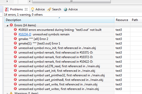
tried this but kept getting error.

    thanks.

  • hi, 

    i have already set the USCIARMP,  , but there is still no data coming in or going out. 

    this is the debug mode, 

    thanks. 

  • Just to be clear: The model in uart_01 is that you type something into PuTTY, and the MSP430 sends (echoes) it back to you. It won't do anything if you don't type something at your PC.

    I was curious what the debugger shows if you pause it (two vertical bars, up at the top) -- where is it executing?

    Also, if you set a breakpoint in the ISR (and then type something), do you get there?

  • hi, 

    thats what i want to achieve, typing something into Putty and get back the data at CCS platform. 

    when pause, nothing happen, no values nothing.


    set break point at ISR and type some things but nothing happened.


    and i realize the code kept getting stuck at line 126,  __bis_SR_register(LPM3_bits|GIE); // Enter LPM3, interrupts enabled.

  • I just noticed this, which I don't recall seeing in other uart_01 variants:

    > // To test code in LPM3, disconnect the debugger.

    This seems a bit odd since the USCI is supposed to start SMCLK automatically even in LPM3. All the same, you might try using LPM0 instead, i.e. change:

    > __bis_SR_register(LPM3_bits|GIE);         // Enter LPM3, interrupts enabled

    to this:

    > __bis_SR_register(LPM0_bits|GIE);         // Enter LPM0, interrupts enabled

  • hi, 

     , still the same, still stuck. without typing anything in Putty, it will stop here, __bis_SR_register(LPM0_bits|GIE); // Enter LPM0, interrupts enabled. after typing some numbers in Putty, its still at the same line. 

  • The LPM line is where I would expect it to Pause. That's a spot-check to make sure the program didn't end up stuck someplace unexpected.

    I don't have your equipment, but at this point I would be probing the RXD line into the MCU with a scope, or even (in a pinch) an LED, to see if there's a disconnect somewhere.

    I'll throw this in: Make sure the Flow Control in PuTTY is set to None. Every so often I forget this and then wonder why my UART is stuck.

  • hi, 

    i'm abit confused but shouldn't the code start running after i input some thing in Putty (interrupt)? 

    changed the Flow control in putty but still having no results.

    will use the scope to test and update back.

    thank you.

  • When you type something the code should very briefly visit the ISR  and then return to the LPM statement. The breakpoint in the ISR should catch this; since it doesn't, that implies that there's something keeping the UART from seeing the byte.

    [Edit: I just zoomed one of your screenshots and it looks like there are characters in your PuTTY window. Do you have local echo turned on?]

  • hi, 

    i have used the oscilloscope to test whenever i am inputting data through TeraTerm, the results shows that the data is being received. its only when i use a scope then im able to see the data. for the past few days i've been trying to see the data at the CCS platform thats why i am stuck. 

    i am now facing a new problem (MSP430: Error connecting to the target: Unknown device) which i have again posted at the forum for help. 

    anyway, thank you so much for your help for the past few days. 

**Attention** This is a public forum