This thread has been locked.

If you have a related question, please click the "Ask a related question" button in the top right corner. The newly created question will be automatically linked to this question.

CCS/MSP430FR5969: I2C - Multisend byte problem, after sending the second byte, the STOP condition appears (it should not)

Part Number: MSP430FR5969
Other Parts Discussed in Thread: MSP430FR5992

Tool/software: Code Composer Studio

Hi, 

I'm trying to send mulitbytes by I2C as master. If it gives you more information, as a slave i'm using pressure sensor MPRLS0025PA00001AB
I was based on the example provided by TI. 


The first byte is sent correctly. The other usually too. However, when trying to send byte 3, the STOP condition appears and the UCB0TXIFG flag does not appear, so I cannot send the next byte. I don't know where the STOP condition appears because in the configuration I set it not to be generated automatically. 

If you need any explanation just ask me. 

It's my code

void main(void)
{
    WDT_A_hold(WDT_A_BASE);

    
    CS_setDCOFreq(CS_DCORSEL_0,CS_DCOFSEL_0);                               //Set DCO frequency to 1MHz
    CS_initClockSignal(CS_ACLK,CS_VLOCLK_SELECT,CS_CLOCK_DIVIDER_1);        //Set ACLK = VLO with frequency divider of 1
    CS_initClockSignal(CS_SMCLK,CS_DCOCLK_SELECT,CS_CLOCK_DIVIDER_1);       //Set SMCLK = DCO with frequency divider of 1
    CS_initClockSignal(CS_MCLK,CS_DCOCLK_SELECT,CS_CLOCK_DIVIDER_1);        //Set MCLK = DCO with frequency divider of 1

    /*
    * Select Port 1
    * Set Pin 6, 7 to input Secondary Module Function, (UCB0SIMO/UCB0SDA, UCB0SOMI/UCB0SCL).
    */
    GPIO_setAsPeripheralModuleFunctionInputPin(
        GPIO_PORT_P1,
        GPIO_PIN6 + GPIO_PIN7,
        GPIO_SECONDARY_MODULE_FUNCTION
    );

    /*
     * Disable the GPIO power-on default high-impedance mode to activate
     * previously configured port settings
     */
    PMM_unlockLPM5();

    EUSCI_B_I2C_initMasterParam param = {0};
    param.selectClockSource = EUSCI_B_I2C_CLOCKSOURCE_SMCLK;
    param.i2cClk = CS_getSMCLK();
    param.dataRate = EUSCI_B_I2C_SET_DATA_RATE_100KBPS;
    param.byteCounterThreshold = 0;
    param.autoSTOPGeneration = EUSCI_B_I2C_NO_AUTO_STOP;
    EUSCI_B_I2C_initMaster(EUSCI_B0_BASE, &param);

    //Specify slave address
    EUSCI_B_I2C_setSlaveAddress(EUSCI_B0_BASE,
                SLAVE_ADDRESS
                );

    //Set Master in receive mode
    EUSCI_B_I2C_setMode(EUSCI_B0_BASE,
                EUSCI_B_I2C_TRANSMIT_MODE
                );

    //Enable I2C Module to start operations
    EUSCI_B_I2C_enable(EUSCI_B0_BASE);

    EUSCI_B_I2C_clearInterrupt(EUSCI_B0_BASE,
                EUSCI_B_I2C_NAK_INTERRUPT
                );

    //Enable master Receive interrupt
    EUSCI_B_I2C_enableInterrupt(EUSCI_B0_BASE,
                EUSCI_B_I2C_NAK_INTERRUPT
              );
    while(1)
    {
        while (EUSCI_B_I2C_SENDING_STOP == EUSCI_B_I2C_masterIsStopSent
                (EUSCI_B0_BASE));

        EUSCI_B_I2C_masterSendMultiByteStart(EUSCI_B0_BASE,
                0x30);

        EUSCI_B_I2C_masterSendMultiByteNext(EUSCI_B0_BASE, 0xAA);

        EUSCI_B_I2C_masterSendMultiByteNext(EUSCI_B0_BASE, 0x00);

        EUSCI_B_I2C_masterSendMultiByteNext(EUSCI_B0_BASE, 0x00);

        EUSCI_B_I2C_masterSendMultiByteStop(EUSCI_B0_BASE);

        __delay_cycles(50);
    }
}

  • >        EUSCI_B_I2C_masterSendMultiByteStart(EUSCI_B0_BASE, 0x30);

    Don't send the SLA byte, since the I2C unit will do that for you.

    The only "commands" I see described are 0xAA (measure) and 0xF0 (NOP). My guess is that the device is NACKing the command byte (0x30). I think one can interpret User Guide (SLAU367O) Fig 32-12 to say that the I2C unit automatically does a Stop Condition on an (unexpected) NACK.

    In any case, you don't want to do this.


  • I deleted this line and as a first command I send 0xAA. But it's not a solution. 

    I connected oscilloscope to SDA line and I can see that after sending 3 byte (0xAA, 0x00, 0x00), the clock is constantly generated and data is being sent. 

    EUSCI_B_I2C_masterSendMultiByteStop(EUSCI_B0_BASE);

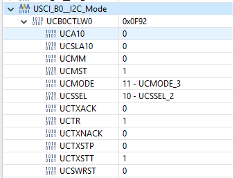
    I set the breakpoint after that func and this is what the registers look like.

    The function listed above should reset UCTXSTT and set UCTXSTP. 
    All tips are welcome :)

    Paulina
  • This does seem an odd set of status for that point in the code. (I suppose it could be a "debugger illusion".) What do UCB0IFG and UCB0STATW look like?

    The only other thing I can think of is that, by sending a Sample command at ~200usec intervals, you're overrunning the device per datasheet (32332628-F-EN|F) Sec 6.6.1 , which specifies a 5ms sample time. This is only half-a-theory since I don't see a path from that to your symptom.

  • Hi, 

    I solved the problem with I2C. If anyone is intrested the code is below. 

    Now I have another problem. Project is working properly when I'm using EUSCI_B0 module. When I'm trying to change B0 to B1 nothing could be send from Master to Slave. 
    I've changed all ...B0... to ...B1... and P1.6 P1.7 to P5.0 P5.1 
    Connections in both module are the same, because I'm using the same Slave (resistors 10kOhm). 
    Should I change something else? 

    Could you please look at both code? 
    Waiting for any tips. 

    B0_I2C_transmit_receive.zip

    B1_I2C_transmit_receive.zip

  • As I read the MSP430FR5969 data sheet (SLAS704G) Fig 1-1, that device doesn't have UCB1 (nor P5).

    Did you switch MCUs?

  • I changde MCU to MSP430FR5992 and I fixed the problem with USCIB1. 

    I read more carefully the datasheet and I changed pin (P5.0 P5.0) configuration to primary module function (before it was secondary).

    So If someone is needed, I2C is working good in my project above. You should only change one function like below:

        GPIO_setAsPeripheralModuleFunctionInputPin(
                GPIO_PORT_P5,
                GPIO_PIN0 + GPIO_PIN1,
            GPIO_PRIMARY_MODULE_FUNCTION
        );

**Attention** This is a public forum