


Part Number: MSP432E401Y
Other Parts Discussed in Thread: SYSBIOS
Tool/software: Code Composer Studio
Howdy,
I am currently trying to interface a split core hall effect sensor () to a differential ADC channel on my MSP432E401Y. I am having trouble finding the correct scaling for the step size for 1.0 amps. The ADC channel is being sampled 100 times per second, then the average of all 100 samples is being averaged to come up with an average ADC step value and converted to millivolts. The purpose of the ADC channel is to read in a current of wire and convert the voltage readings it's receiving into the current value that will be saved on a micro SD card.
Here is a link to the limited datasheet for the AIMH021 hall effect sensor: https://aimdynamics.com/product/AIMH021-050A-5VT/
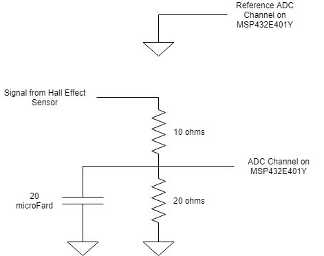
It can output from -5 to 5 volts so I am using a voltage divider of 2/3 to scale the reading to -3.3 to 3.3 range.
The reference voltage for the differential ADC channel is GND but there appears to be a 50 millivolt offset on the GND for the MSP432E401Y Launchpad that is screwing the data.
There is a 10 milifarad capacitor attached from the ADC pin to ground to try and smooth out the noise.
There still seems to be a lot of fluctuation Should there be a low pass filter for the input to the ADC channel?
There is no electronic interface on the AIMH021, just two potentiometers to adjust the reference voltage. I am wondering if someone could point me to some resources that would clean up the ADC signal so it can be read properly.
Here is a diagram of the setup currently for the ADC channel:
Here is a chart of the voltage read by the ADC channel with the corresponding current follwing through the hall effect senor:
Here is the code:
// XDC module Header Files
#include <xdc/std.h> // XDC "base types" - must be included FIRST
#include <xdc/runtime/Types.h> // XDC constants/types used in xdc.runtime pkg
#include <xdc/cfg/global.h> // For all BIOS instances created statically in RTOS .cfg file
#include <xdc/runtime/Log.h> // For any Log_info() call
// TI-RTOS Kernel Header Files
#include <ti/sysbios/BIOS.h> // BIOS module API
#include <ti/sysbios/knl/Task.h> // Task APIs
#include <ti/sysbios/knl/Semaphore.h> // Semaphore APIs
#include <ti/sysbios/knl/Mailbox.h> // Mailbox API
#include <ti/display/Display.h>
/* For usleep() */
#include <unistd.h>
#include <stdint.h>
#include <stddef.h>
#include <stdlib.h>
#include <math.h>
/* Driver Header files */
#include <ti/drivers/GPIO.h>
#include <ti/display/Display.h>
#include <ti/sysbios/knl/Task.h> // Task APIs
#include <ti/sysbios/knl/Semaphore.h>
// #include <ti/drivers/UART.h>
// #include <ti/drivers/Watchdog.h>
#include <semaphore.h>
#include <ti/drivers/ADCBuf.h>
/* Driver configuration */
#include "ti_drivers_config.h"
#include "myMailbox.h"
#define ADCBUFFERSIZE (1000)
#define CONFIG_ADCBUF0CHANNEL_0 0
/* Global variables */
uint32_t hallEffectADCValue;
double current;
extern double hallEffectThreshold;
uint16_t hallEffectAlert;
extern Mailbox_Handle hallEffectSensorMailbox;
extern Display_Handle display;
uint16_t sampleBufferOne[ADCBUFFERSIZE];
uint16_t sampleBufferTwo[ADCBUFFERSIZE];
float voltageBuffer[ADCBUFFERSIZE];
uint32_t buffersCompletedCounter = 0;
/* Display Driver Handle */
Display_Handle display;
/* ADCBuf semaphore */
sem_t adcbufSem;
/* This function converts a differential buffer to signed microvolts*/
int_fast16_t convertAdjustedDifferential(ADCBuf_Handle handle,
uint32_t adcChannel,
void *adjustedSampleBuffer,
float outputDifferentialBuffer[],
uint_fast16_t sampleCount)
{
uint32_t i;
uint16_t *adjustedRawSampleBuf = (uint16_t *) adjustedSampleBuffer;
float refVoltage = 3.3f;
/* Converts the ADC result (14-bit) to a float with respect to refVoltage */
for (i = 0; i < sampleCount; i++)
{
if (adjustedRawSampleBuf[i] == 0x800)
{
outputDifferentialBuffer[i] = 0;
}
else
{
outputDifferentialBuffer[i] = (refVoltage
* (adjustedRawSampleBuf[i] - 0x800)) / 0x800;
}
}
return ADCBuf_STATUS_SUCCESS;
}
/*
* This function is called whenever a buffer is full.
* The content of the buffer is then converted into human-readable format and
* sent to the PC via UART.
*
*/
void adcBufCallback(ADCBuf_Handle handle, ADCBuf_Conversion *conversion,
void *completedADCBuffer, uint32_t completedChannel)
{
/* Adjust raw adc values and convert them to microvolts */
convertAdjustedDifferential(handle, completedChannel, completedADCBuffer,
voltageBuffer, ADCBUFFERSIZE);
/* post adcbuf semaphore */
sem_post(&adcbufSem);
}
/*
* ======== accelerometerThread ========
*
* MSP_EXP432E401Y Accelerometer ADC channels:
* - Hall effect Sensor Signal = adc3 = PE3
*/
void hallEffectSensorTask(UArg a0, UArg a1)
{
HallEffectMsgObj hallEffectData;
ADCBuf_Handle adcBuf;
ADCBuf_Params adcBufParams;
ADCBuf_Conversion continuousConversion;
uint_fast16_t i;
int32_t status;
/* Call driver init functions */
ADCBuf_init();
status = sem_init(&adcbufSem, 0, 0);
if (status != 0)
{
Display_printf(display, 0, 0, "Error creating adcbufSem\n");
while (1)
;
}
Display_printf(display, 0, 0, "Starting the ADCBuf differential example");
/* Set up an ADCBuf peripheral in ADCBuf_RECURRENCE_MODE_CONTINUOUS */
ADCBuf_Params_init(&adcBufParams);
adcBufParams.callbackFxn = adcBufCallback;
adcBufParams.recurrenceMode = ADCBuf_RECURRENCE_MODE_CONTINUOUS;
adcBufParams.returnMode = ADCBuf_RETURN_MODE_CALLBACK;
adcBufParams.samplingFrequency = 1000;
adcBuf = ADCBuf_open(HALLEFFECT_ADCBUF0, &adcBufParams);
/* Configure the conversion struct */
continuousConversion.arg = NULL;
continuousConversion.adcChannel = CONFIG_ADCBUF0CHANNEL_0;
continuousConversion.sampleBuffer = sampleBufferOne;
continuousConversion.sampleBufferTwo = sampleBufferTwo;
continuousConversion.samplesRequestedCount = ADCBUFFERSIZE;
if (!adcBuf)
{
/* AdcBuf did not open correctly. */
while (1)
;
}
/* Start converting. */
if (ADCBuf_convert(adcBuf, &continuousConversion,
1) != ADCBuf_STATUS_SUCCESS)
{
/* Did not start conversion process correctly. */
while (1)
;
}
/*
* Go to sleep in the foreground thread forever. The data will be collected
* and transfered in the background thread
*/
while (1)
{
sem_wait(&adcbufSem);
/*
* Start with a header message and convert each entry in the current buffer
* to a human-readable format
*/
double averageCurrent = 0;
double sumVoltage = 0;
double averageVoltage = 0;
int sumADCStep = 0;
int averageADCStep = 0;
for (i = 0; i < ADCBUFFERSIZE; i++)
{
sumVoltage = sumVoltage + voltageBuffer[i];
}
/*Calculated voltage average*/
averageVoltage = (sumVoltage / ADCBUFFERSIZE) + 0.5004;
for (i = 0; i < ADCBUFFERSIZE; i++)
{
sumADCStep = sumADCStep + sampleBufferOne[i];
}
/*Calculated ADC Steps average*/
averageADCStep = (sumADCStep / ADCBUFFERSIZE);
/*Calculate the Current from the step average*/
//averageCurrent = 0.0166*averageADCStep - 35.1;
// averageCurrent = (4.54*(averageVoltage*averageVoltage))+4.91*(averageVoltage)-0.106;
//averageCurrent = -0.0701*pow(averageVoltage,4)+1.81*pow(averageVoltage,3)+1.71*pow(averageVoltage,2)+5.95*(averageVoltage)-0.084;
//averageCurrent = ((double)averageADCStep - 2079.00)/71.00;
averageCurrent = -570*pow(averageVoltage,6)+766*pow(averageVoltage,5)-290*pow(averageVoltage,4)+49.5*pow(averageVoltage,2)+43.8*(averageVoltage)+1.7;
Display_printf(display, 0, 0, "Average Voltage: %4.4d Steps, Average Voltage: %4.4f V, Average Current: %4.4lf",
averageADCStep, averageVoltage, averageCurrent);
// Set the alarm if one of the ADC is above their thresholds
hallEffectData.currentSensed = 0;
if (current >= hallEffectThreshold)
{
hallEffectData.currentSensed = 1;
}
else
{
hallEffectData.currentSensed = 0;
}
/* Store current data in hall effect mailbox to store on microSD and
* send updates.
*/
//hallEffectData.currentMagnitude = hallEffectCurrent;
Mailbox_post(hallEffectSensorMailbox, &hallEffectData,
BIOS_WAIT_FOREVER);
Task_sleep(200);
}
}
