This thread has been locked.

If you have a related question, please click the "Ask a related question" button in the top right corner. The newly created question will be automatically linked to this question.

CCS/MSP430F5659: CCS V8 Error Connecting to target. unknown device.

Part Number: MSP430F5659


Tool/software: Code Composer Studio

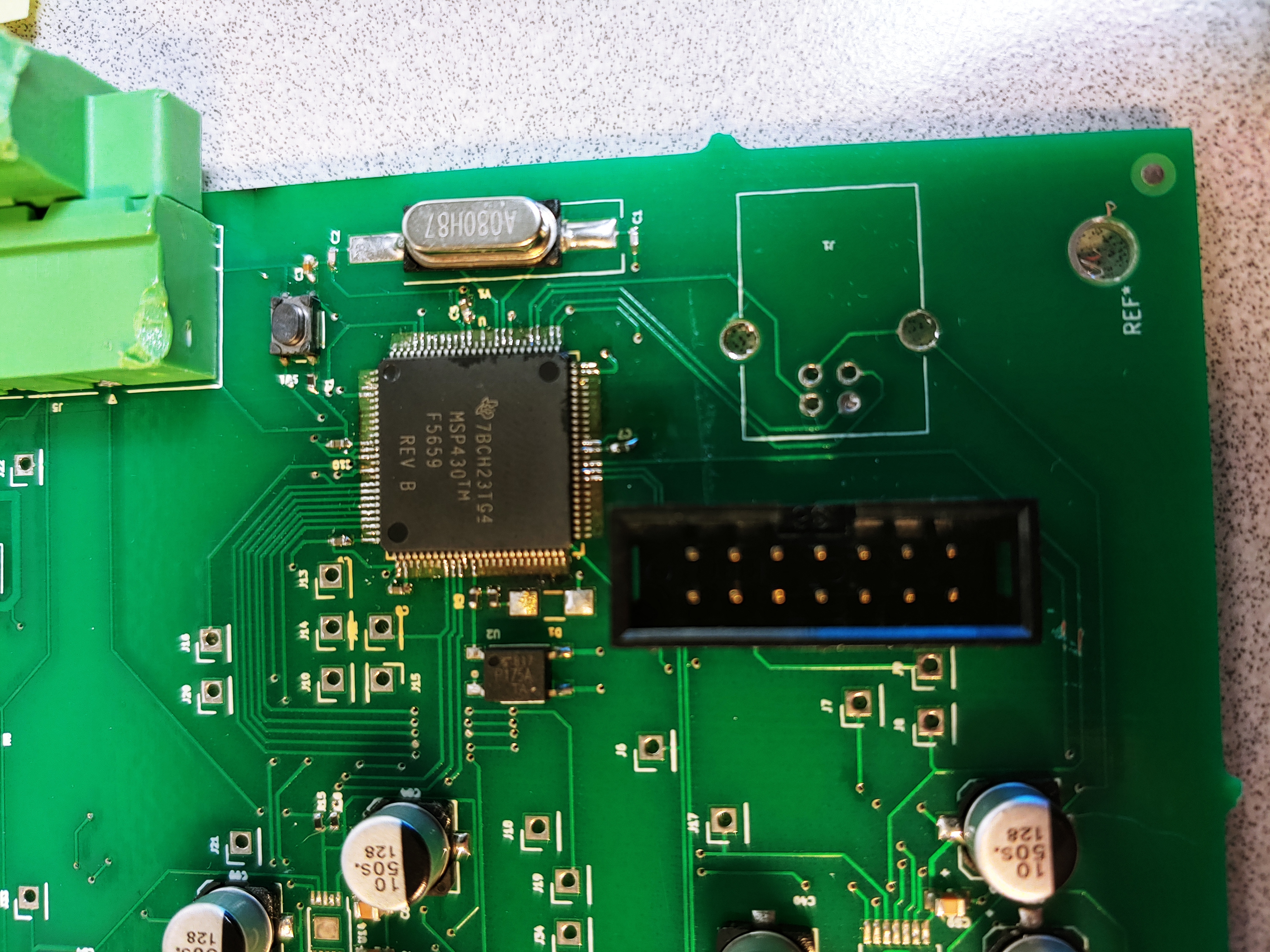
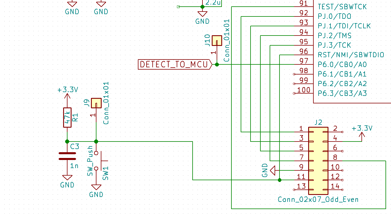
I have a MSP430F5659 on a custom board that I can't connect to. I am using a MSP-FET430UIF debugger connected the the micro-controller in the following manner,

I am fresh out of ideas. I should mention that I have replaced the micro-controller with no success and do have one design that is exactly the same which is working. I suppose the problem is the ability to connect via JTAG is sporadic.

  • Hi Allan,

    Everything seems to be correct on the schematic so I don't see any issues there. The only parameter that may be having an impact on your ability to program the device successfully is the capacitance on the RST line. The capacitance on that line impact the rise/fall times of the pin and in some cases may need to be tweaked based on individual board design.

    I would recommend replacing the 1nF capacitor with a 2.2nF capacitor and see if that fixes your issue.

    If you do come to determine that the capacitor value does not impact the programming capability then perhaps the issue is not at the board level. Does the programmer consistently program other boards successfully (where the only change in your test setup is switching the board)?

    Best regards,

    Matt

  • Matt,

    I replaced the C3 capacitor with a 2.7nF capacitor and the problem still persists. Maybe some other component has damaged the microcontroller? To test that theory I have removed all other IC and will replace the MSP430 again. I'll update if that works.

    Thanks,

    Allan

  • Allan,

    2.7nF exceeds the specification highlighted in the MSP430 Hardware Tools User's Guide for 4-wire JTAG communication (Figure 2-1) which states that the capacitor should not be above 2.2nF

    That could be the reason why you are still unable to program the device.

    Best regards,

    Matt

  • Matt,

    I managed to find a 2.2nF. This didn't fix the problem.

    Thanks,

    Allan

  • Allan,

    So now that there doesn't seem to be any issue with the schematic, have you been able to confirm that the programmer and computer consistently programs other boards successfully (where the only change in your test setup is switching the board)?

    Best regards,

    Matt

  • Matt,

    Yes I am able to program the board that works consistently. I suppose I should mention that the board which works and the board that doesn't work are manufactured by two different suppliers.

    Thanks,

    Allan

  • Allan,

    That is good information to know! If the only difference between the two testing setups is the board itself, that would lead me to believe that the issue lies somewhere in the target HW. You have a board from supplier 1 that is not able to be programmed and a board from supplier 2 that is consistently programmable. Is the schematic and layout for both boards exactly the same or are these different designs?

    For the board that is not working, are you able to probe the signals from the programming pins to the MCU to ensure that the programming signals are actually making it to the MCU and that all of the power pins are at the correct voltage levels?

    -Matt

  • Matt,

    Is the schematic and layout for both boards exactly the same or are these different designs?


    Yes the schematic and layout for both boards is exactly the same.


    Below is a screen shot of the JTAG signals going to the microcontroller.

    • Channel 1 TDO
    • Channel 2 TDI
    • Channel 3 TMS
    • Channel 4 TCK


    I have also attached a CSV file of these measurements.

    Newfile1.csv

    Thanks,


    Allan

  • Allan,

    I'm not seeing any issues at the moment. Were you able to confirm the MCU's power pins are at the appropriate voltage level?

    Could you please provide top-side pictures of both boards?

    Best regards,

    Matt

  • Matt,

    Here is a picture of both boards.

    Below is a picture of the board that does not work.

    Below is a picture of the board that does work.

  •  Matt,

    I also checked the power pins, they are all at 3.3V, but I still can't program the MCU.

    Thanks,

    Allan

  • Allan,

    Judging from the pictures you provided, the chip soldering on the board that does not work looks very different compared to the chip soldering on the board that does work. There may be signals that are not connected properly through the solder connections.

    I think the issue might be with the assembly of the board itself and not the device on the board. Are you able to try swapping the devices to see if the problem follows the device or to confirm that the problem stays with that specific board?

    Best regards,

    Matt

  • Matt,

    I replaced the MCU on the board that does not work this morning. So I am pretty sure it must be the board traces. I will try and solder some wires to the pins of the MCU to see what kind of signals we get on JTAG.

    Thanks,

    Allan

  • Allan,

    If the issue is in fact a problem with the manufacturing of your board then you may want to work with your board manufacturer to address this problem with the traces and/or assembly work.

    Best regards,

    Matt

**Attention** This is a public forum