This thread has been locked.

If you have a related question, please click the "Ask a related question" button in the top right corner. The newly created question will be automatically linked to this question.

CCS/MSP-EXP432E401Y: using CAN in network_terminal

Part Number: MSP-EXP432E401Y

Tool/software: Code Composer Studio

Hi,

i'm using two MSP-EXP432E401Y with two BOOST-CC3135. The two LaunchPads are connected with CAN transceivers to the same bus. I want to send a CAN frame from one device to the other over the bus and then send it back via Wi-Fi. For that i'm using the network_terminal example.

For sending and receiving CAN i created two functions (see code below). I use the same code as in the CAN_singlemessage_receive/transmit examples, but with CAN1 instead of CAN0. The TCP-Server-device will call the CANRXConfig function at the beginning of the TCPServer-function. It will then configure the CAN and will repeatedly print "rxMsg" to the console (line 27) until a CAN message will arrive. The TCP-Client-device will call the CANTXConfig-function at the beginning of the TCPClient-function for sending the CAN frame.

What happens is that after typing the "recv" command with the TCP-Client-device, the TCP-Server-device stops printing "rxMsg" to the console. This could mean that a CAN message arrived, but then it should print a "1" to the console (line 30). Which it doesn't. And after sending the CAN frame the TCP-Client-device will only print the first 4 bytes of the frame sent although it is 8 bytes long (see Console picture). When i have a oscilloscpe available tomorrow i will try to measure the CAN message to make sure it is send.

Functions for sending and receiving the CAN frame:

void CANRXConfig(void)
{
    /* Run from the PLL at 120 MHz */
    sysClock = MAP_SysCtlClockFreqSet((SYSCTL_XTAL_25MHZ |
                SYSCTL_OSC_MAIN | SYSCTL_USE_PLL |
                SYSCTL_CFG_VCO_480), 120000000);

    configureCAN();

    /* Initialize message object 1 to be able to receive CAN message ID 0x100 */
    sCANRX.ui32MsgID = 0x100;
    sCANRX.ui32MsgIDMask = 0;

    /* Enable interrupt on RX */
    sCANRX.ui32Flags = MSG_OBJ_RX_INT_ENABLE;

    /* Size of message is 8 */
    sCANRX.ui32MsgLen = sizeof(CANRX);

    /* Load the message object into the CAN peripheral. Once loaded an
     * interrupt will occur only when the CAN ID is 0x100. Use message
     * object 1 for receiving messages */
    MAP_CANMessageSet(CAN1_BASE, 1, &sCANRX, MSG_OBJ_TYPE_RX);

    while(1)
    {
        UART_PRINT("%d\n\r", rxMsg);
        if (rxMsg)
        {
            UART_PRINT("%d\n\r", rxMsg);
            /* Re-use the same message object that was used earlier to configure
             * the CAN */
            sCANRX.pui8MsgData = (uint8_t *)&CANRX;

            /* Read the message from the CAN */
            MAP_CANMessageGet(CAN1_BASE, 1, &sCANRX, 0);

            /* Check the error flag to see if errors occurred */
            if (sCANRX.ui32Flags & MSG_OBJ_DATA_LOST)
            {
                UART_PRINT("\nCAN message loss detected\n");
            }
            else
            {
                UART_PRINT("CAN received: %u %u %u %u %u %u %u %u\n\r", CANRX[0],CANRX[1],CANRX[2],CANRX[3],CANRX[4],CANRX[5],CANRX[6],CANRX[7]);
            }
            rxMsg = false;
        }
    }
}

void CANTXConfig(void)
{
    /* Run from the PLL at 120 MHz */
    sysClock = MAP_SysCtlClockFreqSet((SYSCTL_XTAL_25MHZ |
                SYSCTL_OSC_MAIN | SYSCTL_USE_PLL |
                SYSCTL_CFG_VCO_480), 120000000);

    configureCAN();

    /* Initialize message object 1 to be able to send CAN message 1 */
    sCANTX.ui32MsgID = 0x100;

    /* No mask needed for TX */
    sCANTX.ui32MsgIDMask = 0;

    /* Enable interrupt on TX */
    sCANTX.ui32Flags = MSG_OBJ_TX_INT_ENABLE;

    /* Size of message is 8 */
    sCANTX.ui32MsgLen = sizeof(CANTX);

    /* Ptr to message content */
    sCANTX.pui8MsgData = CANTX;

    /* Send the CAN message using object number 1 */
    MAP_CANMessageSet(CAN1_BASE, 1, &sCANTX, MSG_OBJ_TYPE_TX);

    /* Check the error flag to see if errors occurred */
    if(errFlag)
    {
        UART_PRINT(" error - cable connected?\n");
    }
    else
    {
        UART_PRINT("CAN sent: %u %u %u %u %u %u %u %u\n\r", CANTX[0],CANTX[1],CANTX[2],CANTX[3],CANTX[4],CANTX[5],CANTX[6],CANTX[7]);
    }
    while(1)
    {

    }
}

Regards

Christoph

  • Hi,

    i have done some more testing and measuring with an oscilloscope. It seems that the device has some problems with the bus timing when only sending once on an empty bus. There i measured only 2 - 3 small pikes, nothing else. After putting a loop around  "MAP_CANMessageSet" i can see the CAN frames on the scope. I think i'm good for now, this is something i can continue working with. Thanks.

    Regards

    Christoph

  • Hi,

    I somehow managed that the CAN message is actually send by the device and i was able to capture it with the scope.

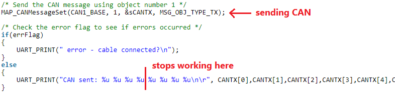
    But now i still have the problem that both devices stop working after the CAN message is send. Both devices stop while performing a UART_PRINT as you can see in the terminal. The receiving device always stop at a different position in the UART_PRINT dependant on when i send the CAN message. The transmitting device always stops at the same char, the first "s" from "successful". What can cause such problem?

    The code changed slightly. The transmitting part:

    /* Send the CAN message using object number 1 */
        UART_PRINT("sending CAN message...\n\r");
        MAP_CANMessageSet(CAN1_BASE, 1, &sCANTX, MSG_OBJ_TYPE_TX);
    
        /* Check the error flag to see if errors occurred */
        if(errFlag)
        {
            UART_PRINT(" error - cable connected?\n");
        }
        else
        {
            UART_PRINT("CAN message sent successful: %u %u %u %u %u %u %u %u\n\r", CANTX[0],CANTX[1],CANTX[2],CANTX[3],CANTX[4],CANTX[5],CANTX[6],CANTX[7]);
        }

    The receiving part:

    while(1)
        {
            UART_PRINT("Waiting for incoming CAN message. rxMsg = %d\n\r", rxMsg);
            if (rxMsg == true)
            {
                UART_PRINT("Message arrived. rxMsg = %d\n\r", rxMsg);
    
                /* Re-use the same message object that was used earlier to configure
                 * the CAN */
                sCANRX.pui8MsgData = (uint8_t *)&CANRX;
    
                /* Read the message from the CAN */
                MAP_CANMessageGet(CAN1_BASE, 1, &sCANRX, 0);
    
                /* Check the error flag to see if errors occurred */
                if (sCANRX.ui32Flags & MSG_OBJ_DATA_LOST)
                {
                    UART_PRINT("\nCAN message loss detected\n");
                }
                else
                {
                    UART_PRINT("CAN message received: %u %u %u %u %u %u %u %u\n\r", CANRX[0],CANRX[1],CANRX[2],CANRX[3],CANRX[4],CANRX[5],CANRX[6],CANRX[7]);
                }
                rxMsg = false;
            }
        }

    Here are also the configureCAN and IRQHandler i use:

    void configureCAN(void)
    {
        UART_PRINT("");
        /* Configure the CAN and its pins PB0 and PB1 @ 500Kbps */
    
        /* Enable the clock to the GPIO Port B and wait for it to be ready */
        MAP_SysCtlPeripheralEnable(SYSCTL_PERIPH_GPIOB);
        while(!(MAP_SysCtlPeripheralReady(SYSCTL_PERIPH_GPIOB)))
        {
        }
        UART_PRINT("");
        /* Enable CAN1 */
        MAP_SysCtlPeripheralEnable(SYSCTL_PERIPH_CAN1);
    
        /* Configure GPIO Pins for CAN mode */
        MAP_GPIOPinConfigure(GPIO_PB0_CAN1RX);
        MAP_GPIOPinConfigure(GPIO_PB1_CAN1TX);
        MAP_GPIOPinTypeCAN(GPIO_PORTB_BASE, GPIO_PIN_0 | GPIO_PIN_1);
        UART_PRINT("");
    
        /* Initialize the CAN controller */
        MAP_CANInit(CAN1_BASE);
        UART_PRINT("");
        /* Set up the bit rate for the CAN bus.  CAN bus is set to 500 Kbps */
        MAP_CANBitRateSet(CAN1_BASE, sysClock, 500000);
        UART_PRINT("");
        /* Enable interrupts on the CAN peripheral */
        MAP_CANIntEnable(CAN1_BASE, CAN_INT_MASTER | CAN_INT_ERROR | CAN_INT_STATUS);
        
        UART_PRINT("");
        /* Enable the CAN interrupt */
        MAP_IntEnable(INT_CAN1);
        UART_PRINT("");
        /* Enable the CAN for operation */
        MAP_CANEnable(CAN1_BASE);
        UART_PRINT("");
    }
    
    void CAN1_IRQHandler(void)
    {
        uint32_t canStatus;
    
        /* Read the CAN interrupt status to find the cause of the interrupt */
        canStatus = MAP_CANIntStatus(CAN1_BASE, CAN_INT_STS_CAUSE);
    
        /* If the cause is a controller status interrupt, then get the status */
        if(canStatus == CAN_INT_INTID_STATUS)
        {      
            /* Read the controller status.  This will return a field of status
             * error bits that can indicate various errors */
            canStatus = MAP_CANStatusGet(CAN1_BASE, CAN_STS_CONTROL);
    
            /* Set a flag to indicate some errors may have occurred */
            errFlag = true;
        }
    
        /* Check if the cause is message object 1, which what we are using for
         * receiving messages */
        else if(canStatus == 1)
        {
            /* Getting to this point means that the RX interrupt occurred on
             * message object 1, and the message RX is complete.  Clear the
             * message object interrupt */
            MAP_CANIntClear(CAN1_BASE, 1);
    
            /* Increment a counter to keep track of how many messages have been
             * sent. In a real application this could be used to set flags to
             * indicate when a message is sent */
            msgCount++;
    
            /* Set flag to indicate received message is pending */
            rxMsg = true;
    
            /* Since the message was sent, clear any error flags */
            errFlag = false;
        }
        else
        {
            
        }
    }

    Something else i don't understand is, when i remove the UART_PRINT's from the configureCAN function, then the devices get stuck somewhere in this function and won't continue.

    Regards

    Christoph

  • Hello,

    Could you try to debug the code step by step and position where the code get stuck?

    It seems a stack overflow issue.

  • Hello Winter,

    thanks for your help.

    for the CAN transmitting device the relevant code section is the following:

    /* Send the CAN message using object number 1 */
        UART_PRINT("sending CAN message...\n\r");
        MAP_CANMessageSet(CAN1_BASE, 1, &sCANTX, MSG_OBJ_TYPE_TX);
    
        /* Check the error flag to see if errors occurred */
        if(errFlag)
        {
            UART_PRINT(" error - cable connected?\n");
        }
        else
        {
            UART_PRINT("CAN message sent successful: %u %u %u %u %u %u %u %u\n\r", CANTX[0],CANTX[1],CANTX[2],CANTX[3],CANTX[4],CANTX[5],CANTX[6],CANTX[7]);
        }

    Debugging step by step, starting with line 2. Then it opens uart_term.c doing the following code:

    int Report(const char *pcFormat,
               ...)
    {
        int iRet = 0;
        char        *pcBuff;
        char        *pcTemp;
        int iSize = 256;
        va_list list;
    
        pcBuff = (char*)malloc(iSize);
        if(pcBuff == NULL)
        {
            return(-1);
        }

    Then it opens release_pem4f.c and doing:

    static Void *ti_sysbios_rts_MemAlloc_alloc(SizeT size)
    {
        Header *packet;
        xdc_runtime_Error_Block eb;
    
        if (size == 0) {
            return (NULL);
        }
    
        xdc_runtime_Error_init(&eb);

    Then it goes into Error.c:

    Void Error_init(Error_Block *eb)
    {
        if (eb != NULL && eb != &xdc_runtime_Error_IgnoreBlock) {
            (void)memset(eb, 0, sizeof (Error_Block));
        }
    }

    When i'm in line 4 here and make one "step into" then i can see the CAN frame on my scope. The UART_PRINT "sending CAN message..." appears on the terminal, and the UART_PRINT "CAN message sent s" (line 12) appears on the terminal which is not the complete print. And of course it stops working.

    For the CAN receiving device the relevant code is the following:

    while(1)
        {
            UART_PRINT("Waiting for incoming CAN message. rxMsg = %d\n\r", rxMsg);
            if (rxMsg == true)
            {
                //...
            }
        }

    It's permanently printing line 3 where it goes through the same calls as the CAN transmitting device when calling line 2 there. After the CAN frame is send, it goes through the same steps as before and then stops in Error.c at:

    Void Error_init(Error_Block *eb)
    {
        if (eb != NULL && eb != &xdc_runtime_Error_IgnoreBlock) {
            (void)memset(eb, 0, sizeof (Error_Block));
        }
    }

    Then it stops working.

  • Hello,

    From your debug, the error occurs at the memory run-time allocation. This may because the heap size for malloc() is not sufficient.

    Could you increase the heap size in Project Options?

  • Do you mean here?

    What do i have to type in there?

  • Try to give a enough space. For example, 0x400 = 1KB for both heap and stack.

  • I tried different sizes for both, up to 0x40000. I still havel the same problem.

  • Are you using T-RTOS in your project?

  • As main project i use network_terminal tirtos, the code for CAN i use in network_terminal is from CAN_singlemessage-examples which is nortos.

  • In found out that the "CAN1_IRQHandler" is not called, wether on the transmitting device nor on the receiving device after the CAN frame is sent. Is this because of the existing issue, or is it possible that this causes the issue?

  • Shall i open a new thread because it is already marked as "resolved"?

  • So what's the issue right now? UART PRINTF issue or CAN send/receive issue?

    We need test the CAN and UART PRINTF separately to narrow down the issue.

  • Hi Winter,

    the UARTPRINT in general works fine. Sending a CAN message is also working. I can see the valid CAN message on the sniffingtool i use. But after the CAN message is sent, the CAN-receiving device gets interrupted in the middle of its current UARTPRINT as you can see in the image below, and afterwards nothing else happens.

    Kind of the same thing on the sending device. After the CAN-message is sent it stops in the middle of the UARTPRINT directly after the CANMessageSet function. When i remove this UARTPRINT it also doesn't continue with the code much further.

    Terminal:

    I think the cause could be the CAN1_IRQHandler because this is what should be called on both devices after sending the CAN-message. But it isn't called. Maybe there is some Interrupt-configuration missing or something like that. I know that there is some interrupt-configuration in the "startup"-file in the CAN examples, but there is no such file in the network_terminal example.

    Regards

    Christoph

  • The nortos CAN API can't be used in a TI-RTOS project.

    You need used the TI-RTOS version CAN driver, please see the example http://dev.ti.com/tirex/explore/node?node=AMD1IttEGaIGy1CYJ0Bsvw__J4.hfJy__LATEST

  • Hi Winter,

    Thanks a lot. I will try it out.

    Best regards

    Christoph

**Attention** This is a public forum