Other Parts Discussed in Thread: MSP430G2231, MAX232
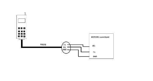
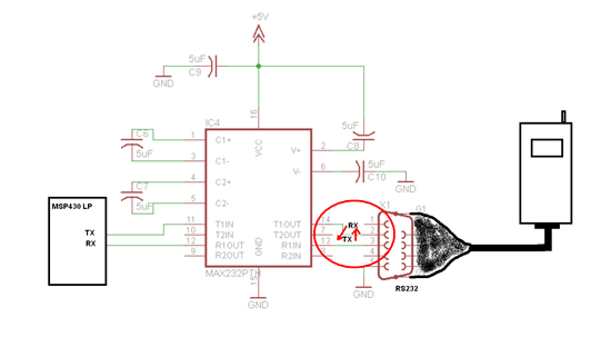
Hi, I'm working on msp430 launchpad. I'm trying make a basic uart. The Code, that I use is a sample code from TI webpage. My project is about remote gsm control device. Actually I'm trying to send a character to hyper terminal. It work properly. But when I plug my phone in via rs232 and I send some AT command to phone it doesn't work. If I connect my phone directly with PC, everything works great. Well, LaunchP --->HyperT=OK, HyperT--->phone=OK, LaunchP--->phone= does not work.
Can u please check my code, if is good? Thank u
CODE:
//******************************************************************************
// MSP430G2xx1 Demo - Timer_A, Ultra-Low Pwr UART 9600 Echo, 32kHz ACLK
//
// Description: Use Timer_A CCR0 hardware output modes and SCCI data latch
// to implement UART function @ 9600 baud. Software does not directly read and
// write to RX and TX pins, instead proper use of output modes and SCCI data
// latch are demonstrated. Use of these hardware features eliminates ISR
// latency effects as hardware insures that output and input bit latching and
// timing are perfectly synchronised with Timer_A regardless of other
// software activity. In the Mainloop the UART function readies the UART to
// receive one character and waits in LPM3 with all activity interrupt driven.
// After a character has been received, the UART receive function forces exit
// from LPM3 in the Mainloop which configures the port pins (P1 & P2) based
// on the value of the received byte (i.e., if BIT0 is set, turn on P1.0).
// ACLK = TACLK = LFXT1 = 32768Hz, MCLK = SMCLK = default DCO
// //* An external watch crystal is required on XIN XOUT for ACLK *//
//
// MSP430G2xx1
// -----------------
// /|\| XIN|-
// | | | 32kHz
// --|RST XOUT|-
// | |
// | CCI0B/TXD/P1.1|-------->
// | | 9600 8N1
// | CCI0A/RXD/P1.2|<--------
//
// D. Dang
// Texas Instruments Inc.
// October 2010
// Built with CCS Version 4.2.0 and IAR Embedded Workbench Version: 5.10
//******************************************************************************
#include "msp430g2231.h"
//------------------------------------------------------------------------------
// Hardware-related definitions
//------------------------------------------------------------------------------
#define UART_TXD 0x02 // TXD on P1.1 (Timer0_A.OUT0)
#define UART_RXD 0x04 // RXD on P1.2 (Timer0_A.CCI1A)
//------------------------------------------------------------------------------
// Conditions for 9600 Baud SW UART, SMCLK = 1MHz
//------------------------------------------------------------------------------
#define UART_TBIT_DIV_2 (1000000 / (9600 * 2))
#define UART_TBIT (1000000 / 9600)
//------------------------------------------------------------------------------
// Global variables used for full-duplex UART communication
//------------------------------------------------------------------------------
unsigned int txData; // UART internal variable for TX
unsigned char rxBuffer; // Received UART character
//------------------------------------------------------------------------------
// Function prototypes
//------------------------------------------------------------------------------
void TimerA_UART_init(void);
void TimerA_UART_tx(unsigned char byte);
void TimerA_UART_print(char *string);
//------------------------------------------------------------------------------
// main()
//------------------------------------------------------------------------------
void main(void)
{
WDTCTL = WDTPW + WDTHOLD; // Stop watchdog timer
DCOCTL = 0x00; // Set DCOCLK to 1MHz
BCSCTL1 = CALBC1_1MHZ;
DCOCTL = CALDCO_1MHZ;
P1OUT = 0x00; // Initialize all GPIO
P1SEL = UART_TXD + UART_RXD; // Timer function for TXD/RXD pins
P1DIR = 0xFF & ~UART_RXD; // Set all pins but RXD to output
P2OUT = 0x00;
P2SEL = 0x00;
P2DIR = 0xFF;
__enable_interrupt();
TimerA_UART_init(); // Start Timer_A UART
// i was trying send at commands as normal letter but also as ascii character, both doesn't work
//here I send AT commands to phone
//TimerA_UART_print("AT");
TimerA_UART_tx(0X65); // letter A
TimerA_UART_tx(0X84); // letter T
TimerA_UART_tx(0X0D); // enter
TimerA_UART_print("atd +4219021***04 \n"); //command for dial number
TimerA_UART_tx(0X0D); // enter
for (;;)
{
// Wait for incoming character
__bis_SR_register(LPM0_bits);
// Update board outputs according to received byte
/*if (rxBuffer & 0x01) P1OUT |= 0x01; else P1OUT &= ~0x01; // P1.0
if (rxBuffer & 0x02) P1OUT |= 0x08; else P1OUT &= ~0x08; // P1.3
if (rxBuffer & 0x04) P1OUT |= 0x10; else P1OUT &= ~0x10; // P1.4
if (rxBuffer & 0x08) P1OUT |= 0x20; else P1OUT &= ~0x20; // P1.5
if (rxBuffer & 0x10) P1OUT |= 0x40; else P1OUT &= ~0x40; // P1.6
if (rxBuffer & 0x20) P1OUT |= 0x80; else P1OUT &= ~0x80; // P1.7
if (rxBuffer & 0x40) P2OUT |= 0x40; else P2OUT &= ~0x40; // P2.6
if (rxBuffer & 0x80) P2OUT |= 0x80; else P2OUT &= ~0x80; // P2.7
*/
// Echo received character
TimerA_UART_tx(rxBuffer);
}
}
//------------------------------------------------------------------------------
// Function configures Timer_A for full-duplex UART operation
//------------------------------------------------------------------------------
void TimerA_UART_init(void)
{
TACCTL0 = OUT; // Set TXD Idle as Mark = '1'
TACCTL1 = SCS + CM1 + CAP + CCIE; // Sync, Neg Edge, Capture, Int
TACTL = TASSEL_2 + MC_2; // SMCLK, start in continuous mode
}
//------------------------------------------------------------------------------
// Outputs one byte using the Timer_A UART
//------------------------------------------------------------------------------
void TimerA_UART_tx(unsigned char byte)
{
while (TACCTL0 & CCIE); // Ensure last char got TX'd
TACCR0 = TAR; // Current state of TA counter
TACCR0 += UART_TBIT; // One bit time till first bit
TACCTL0 = OUTMOD0 + CCIE; // Set TXD on EQU0, Int
txData = byte; // Load global variable
txData |= 0x100; // Add mark stop bit to TXData
txData <<= 1; // Add space start bit
}
//------------------------------------------------------------------------------
// Prints a string over using the Timer_A UART
//------------------------------------------------------------------------------
void TimerA_UART_print(char *string)
{
while (*string) {
TimerA_UART_tx(*string++);
}
}
//------------------------------------------------------------------------------
// Timer_A UART - Transmit Interrupt Handler
//------------------------------------------------------------------------------
#pragma vector = TIMERA0_VECTOR
__interrupt void Timer_A0_ISR(void)
{
static unsigned char txBitCnt = 10;
TACCR0 += UART_TBIT; // Add Offset to CCRx
if (txBitCnt == 0) { // All bits TXed?
TACCTL0 &= ~CCIE; // All bits TXed, disable interrupt
txBitCnt = 10; // Re-load bit counter
}
else {
if (txData & 0x01) {
TACCTL0 &= ~OUTMOD2; // TX Mark '1'
}
else {
TACCTL0 |= OUTMOD2; // TX Space '0'
}
txData >>= 1;
txBitCnt--;
}
}
//------------------------------------------------------------------------------
// Timer_A UART - Receive Interrupt Handler
//------------------------------------------------------------------------------
#pragma vector = TIMERA1_VECTOR
__interrupt void Timer_A1_ISR(void)
{
static unsigned char rxBitCnt = 8;
static unsigned char rxData = 0;
switch (__even_in_range(TAIV, TAIV_TAIFG)) { // Use calculated branching
case TAIV_TACCR1: // TACCR1 CCIFG - UART RX
TACCR1 += UART_TBIT; // Add Offset to CCRx
if (TACCTL1 & CAP) { // Capture mode = start bit edge
TACCTL1 &= ~CAP; // Switch capture to compare mode
TACCR1 += UART_TBIT_DIV_2; // Point CCRx to middle of D0
}
else {
rxData >>= 1;
if (TACCTL1 & SCCI) { // Get bit waiting in receive latch
rxData |= 0x80;
}
rxBitCnt--;
if (rxBitCnt == 0) { // All bits RXed?
rxBuffer = rxData; // Store in global variable
rxBitCnt = 8; // Re-load bit counter
TACCTL1 |= CAP; // Switch compare to capture mode
__bic_SR_register_on_exit(LPM0_bits); // Clear LPM0 bits from 0(SR)
}
}
break;
}
}
//------------------------------------------------------------------------------