Because of the holidays, TI E2E™ design support forum responses will be delayed from Dec. 25 through Jan. 2. Thank you for your patience.

This thread has been locked.

If you have a related question, please click the "Ask a related question" button in the top right corner. The newly created question will be automatically linked to this question.

CCS/MSP430F5529: MSP430F5529LP Program via Spy-Bi-Wire

Part Number: MSP430F5529
Other Parts Discussed in Thread: MSP430F5519

Tool/software: Code Composer Studio

Hi All

I have an MSP430F5529LP and have designed my own PCB with 430F5529.  Now I'd like to program the new MSP430 embedded on the PCB but failed.

Problem description:

1. MSP430F5529LP works fine, the eZ-FET emulator can program the onboard MSP430F5529 when jumpers are connected.

2. I would like to use SBW mode to program my customized PCB embedded 430F5529 and have SBWTCK, SBWTDIO, and GND pins which are connected to identical pins on the launchpad jumpers.

3. The SBWTDIO pin in my customized PCB follows the launchpad schematic; it connects to 3V3 via a 47K Ohm resistor and a 1nF capacitor to GND.

3. My customized PCB is power by USB Vbus 5V but not 3V3/5V from the lauchpad.  I did measure the voltage on my PCB and the voltage was correct.

4. When opening my code project in CCS and pressing debug, it returns me error "Error connecting to the target: Unknown device"

Did I miss anything; Do I need to set anything to activate SBW mode?

Thank you

Vincent

  • Hey Vincent,

    Could you please provide your schematic and a picture of your test setup so that I can look into your issue further?

    Best regards,

    Matt

  • Are you certain the MCU is correctly soldered onto your PCB?  The SBW lines may not be properly connected to the device. Check for solder bridges. This footprint is a challenge for non-machine assembly.  I have made prototype boards with the smaller F5528 using a paste stencil and reflow soldering. 

  • Hi Matt

    Let me attach setup photo and parts of our schematic.

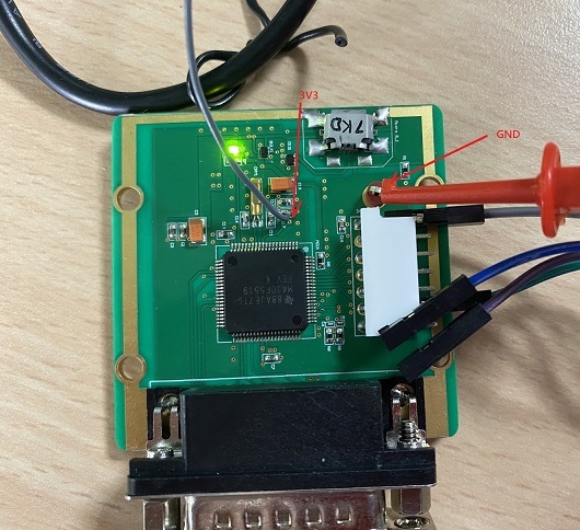
    Full setup.  Both the LP and our PCB are correctly powered.

    Our MCU PCB; we use MSP430F5519.  The PCB is designed for USB Powered.  However, for debug purpose, we soldered the grey wire so that we power it by the 3V3 jumper on the launchpad.

    The white plastic cover contains pin 71 ~ 76 and the BSL pin.

    Part of MCU schematic, we basically just copy the schematic of MSP430F5529LP. 

    Thank you

  • Hi Matt

    Add two comments.

    When opening target configuration file in CCS 8.3.1, the "Test Connection" button is greyed out.

    While when I doing other MSP432R401 projects, I often use "Test Connection" to confirm the debug probe and connection are good.

    I'm new to MSP430 and not sure if this is correct.

    As for solder and contact issue, I have three identical PCBs, none of them is programmable.  I suppose soldering is not the cause.

    Regards

    Vincent

  • Vincent,

    I can easily see that you are correctly connecting the SBWRST and SBWTST signals from the eZ-FET circuitry to the headers on your board, but the rest of the signal connections are difficult to see. Could you explain or show more clearly where you are properly connecting the power and GND lines?

    In general, the shorter the wires are connecting the 2 board together, the better. Voltage drops and parasitic capacitance can lead to programming errors so I would try to keep those wires as short as possible.

    Best regards,

    Matt

  • Hi Matt

    I connect 4 pins between the launchpad and my PCB: GND, 3V3, SBWRST, SBWTST.  I used a 4-pin ribbon cable to connect SBWRST and SBWTST.  The unconnected two pins are out of focus and confuses you.  Actually they are NC. 

    The 3V3 is connected between EZFET_VCC and PCB VCC; GND is also corrected shared between the lauchpad and the PCB.  I measured the voltage of my PCB, the VCC is about 3.29V; I suppose it it OK.  Disconnect the 3V3 connection and power my PCB via USB_VBUS doesn't change the situation, CCS still cannot recognize the MSP5519 and returns me "unknown device".

    Regards

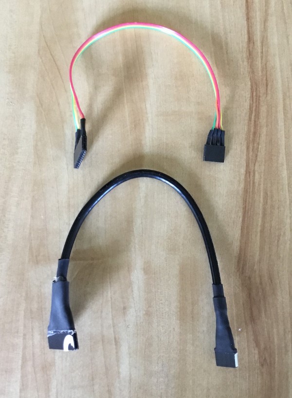
  • I was able to reproduce the problem. As Matt suggested, long jumper wires between the Launchpad and target board appear to be the cause.  I attempted to approximately reproduce the setup shown in the above photos with a FR5969 Launchpad, one of my known good PCBs, and CCS 9.3 running on Ubuntu Linux.  The length of the 4 jumper wires ranged from 20--50 cm. The MSP430 on the target board was not recognized. Then I tried one of my SBW programming cables (see attached photo) that measure ~15 cm. CCS could then connect to the target PCB. When switching cables I had to click Retry a few times, but my short cables always worked. Note that I have a 4-pin header on the target PCB.

  • Vincent,

    It looks like Mike was able to reproduce your issue and validate a solution based on my previous recommendation. Please let us know if you are able to solve this on your end as well.

    Best regards,

    Matt

  • Hi Matt, Mike

    Thank you for providing the information.  Unfortunately, nothing changes after replacing the SBWTCK and SBWTDIO cable with a short one ( < 15cm length).

    On the other hands, I partially solve my problem but don't know the reason behind it.

    I hooked a oscilloscope probe to SBWTDIO to check the signal with a scope.  When a passive scope probe is attached, CCS could program my MSP5519 via the ezFET emulator.

    I suppose it it due to the parallel capacitance of the probe.  Based on page 22 of  slau278 http://www.ti.com/lit/ug/slau278af/slau278af.pdf , it recommends an 1.1nF capacitance (C1 in the figure below) between SBWtDIO and GND. My PCB doesn't have this capacitance, I guess the passive scope probe provides this capacitance.  My probe is a SP200B http://www.ni.com/pdf/dspdf/en/ds-437 by National Instruments, which has 100pF capacitance.

    After that, I unhooked the probe, soldered an 1nF capacitance like the following figure.  However, CCS and the launchpad still cannot recognize the modified PCB unless the scope probe is attached.

    I have no idea about it and will try other capacitance value or scope probes.

    Regards

  • Vincent,

    I does look like you are narrowing down the root cause of the issue here. Moving forward, it is best to keep all fly wire connections the same length and as short at possible to reduce the chances of device miscommunication.

    In your case, it looks like the capacitance on the RST line (SBWTDIO) is causing the inability to recognize the device. According to that hardware tools user's guide you referenced: "The range for C1 can vary between 0.1 nF and 2.2 nF depending on SBW speed, voltage, and board design." The capacitor used on our Launchpad is selected for that specific board design and you may need to tweak it based on your setup; especially taking into account that you are trying to use jumper wires for testing.

    Best regards,

    Matt

  • Hi Matt, Mike

    I talked with my hardware-focus colleague and added another 600K Ohm resistor between SBWTDIO and GND.  Now it is SBWTDIO serial with (a resistor parallel with a capacitor) and it works.

    Thank you for the help and please close this thread.

    Regards

**Attention** This is a public forum