Part Number: MSP430G2553
/*
Hi, I have a problem with TA0CCR1. Let me explain what I want to do.
LED in BIT1 every 800 counts, ON-OFF
LED in BIT6 every 16000 counts, ON-OFF.
LED in BIT6 work but BIT1 dont work.
CCR1 intterupt vektor case 2 dont work.Why?
/*I tried these. But it didn't work again
TA0CCTL1 &= ~CCIFG;
TA0CCTL1 =TA0CCTL1+8000 ;
pls help me.where am i doing wrong?
(I have reviewed the user manual but still have not
been able to solve the problem. I have tried
to solve this problem for 7 hours but I could
not succeed.mps430 timer module it is very complicated.) */
mycode is here ;
#include <msp430.h>

 int main(void) {

     WDTCTL = WDTPW | WDTHOLD;   // Stop watchdog timer

     BCSCTL1 &= ~XTS;
     BCSCTL3 &= ~LFXT1S0;
     BCSCTL3 |= LFXT1S1;  //ACKL setup


    P1DIR |= BIT6+BIT1;  //P1.1 and P1.6 output

    TA0CTL |= MC_1 + TASSEL_1 + TAIE; // up mode-source ACLK 16Khz-Timer innterrupt inable

    TA0CCTL1|=CCIE; //CC interrupt inable

    TA0CCR0=16000;

    TA0CCR1=8000;


    __bis_SR_register( GIE); // general innterrupt inable

}

 #pragma vector=TIMER0_A1_VECTOR
__interrupt void TA0_kesme_func(void)
 {
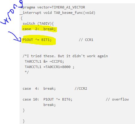
  switch (TA0IV){
  case  2:  break;

  P1OUT ^= BIT1;             // CCR1


  /*I tried these. But it didn't work again
   TA0CCTL1 &= ~CCIFG;
   TA0CCTL1 =TA0CCR1+8000 ;
   */


  case  4:  break;         //CCR2

  case 10:  P1OUT ^= BIT6;                // overflow
            break;
  }

  }