This thread has been locked.

If you have a related question, please click the "Ask a related question" button in the top right corner. The newly created question will be automatically linked to this question.

Compiler/MSP430G2553: Interfacing ADE7753 with MSP430G2553

Part Number: MSP430G2553
Other Parts Discussed in Thread: ENERGIA

Tool/software: TI C/C++ Compiler

Hi Guys, I´m working to interface the ADE7753, from Analog Devices, with MSP430G2553. I´m using Energia IDE. I have several doubts how to do it! 

Someone can share part of the code with me to give a direction to do it?

Best Regards

Alex

  • Hi Alex, thanks for your post. on startup of Energia, Please refer to this page the basic example on MSP430G2 Launchpad.

  • Hi Xiaodong, thanks a lot for your response!

    I´m already using the Energia Library but I didn't have success to connect My MSP430G2553 with ADE7753 via SPI, I change bound rate and SPI mode to check and also I didn't have success. I share here my code. 

    i hope somebody might have done the interface before and let me know one first direction to do it!

    Best Regards,

    Alex

    // the sensor communicates using SPI, so include the library:
    #include <SPI.h>
    #include "Energia.h"
    
    //REGISTRADORES ADE7753 - Sensor's memory register addresses:
    #define MODE 0x09
    #define STATUS 0x0B
    #define RSTSTATUS 0x0C
    #define IRMS 0x16
    #define VRMS 0x17
    #define PERIOD 0x27
    #define AENERGY 0x02
    #define VAENERGY 0x05
    
    const byte READ = 0b00000000;   // ADE7753 read command
    const byte WRITE = 0b10000000;  // ADE7753 write command
    
    /* DIN = MOSI - 17 - VERDE
     *  DOUT = MISO - 19 - AMARELO
     * CS = SS - 17 - AZUL
     * SCLK = SCLK - 18 - LARANAJA
     * CS - chipSelectPin - to digital pin 9  (SS pin) P2.1 - AZUL
     * SIMO / MOSI is Pin 1.7 - VERDE
     * SOMI / MISO is Pin 1.6 - AMARELO
     * CLK - to digital pin 7 (SCLK pin) P1.5 - LARANJA
     */
    
    
    //Pin declarations Sensor and correlated at MSP430G2
    #define DATAOUT 15//MOSI - 20 DIN - MOD. ADE7753 - VERDE 
    #define DATAIN  14//MISO - 19 DOUT - MOD. ADE7753 - AMARELO
    #define SPICLOCK  7//sck - 18 - MOD. ADE7753 - LARANJA
    #define SLAVESELECT 9// chipSelect - 17 MOD. ADE7753 - AZUL
    
    void setup()
    {
        // put your setup code here, to run once:
        Serial.begin(9600);
         // start the SPI library:
        SPI.begin();
        SPI.setDataMode(SPI_MODE0); // CPOL =0 and CPHA =0 
        // initialize the  data ready and chip select pins:
        //SPI.setBitOrder(MSBFIRST);
        SPI.setClockDivider(4); // the command is to use SPI =  or 4 MHz
        pinMode(SLAVESELECT, OUTPUT);
        pinMode(DATAOUT, OUTPUT);
        pinMode(DATAIN, INPUT);
        //pinMode(SPICLOCK,OUTPUT);
        digitalWrite(SLAVESELECT, HIGH);    
        delay(100);
    }
    
    void loop(){
        digitalWrite(SLAVESELECT, LOW);
        SPI.transfer (READ);  // has bits set for a read or write command, and the register address
        digitalWrite(SLAVESELECT, HIGH);
        //SPI.endTransaction();
        delay(100);
        digitalWrite(SLAVESELECT, LOW);
        long regRead = SPI.transfer(IRMS); // read a register
        //SPI.transfer (registerData); // or data to write into a register
        digitalWrite(SLAVESELECT, HIGH);
        //SPI.endTransaction();
        delay(100);
    }

  • >     long regRead = SPI.transfer(IRMS); // read a register

    This just sends the first byte of the transaction. To read a 24-bit result, you need 3 more bytes. [Ref ADE7753 Data sheet (Rev C) Figs 90 and 94]. This would look something like:

    unsigned char hi, mid, lo;  // 3 successive bytes over the SPI
    unsigned long regRead;      // pasted together
    (void)SPI.transfer(IRMS);   // read-register request byte
    hi = SPI.transfer(0x00);    // Write dummy byte, read high byte,
    mid = SPI.transfer(0x00);   // middle byte,
    lo = SPI.transfer(0x00);    //  low byte
    regRead = ((unsigned long)hi << 2*8) | ((unsigned long)mid << 1*8) | ((unsigned long)lo << 0*8); // Paste

    Since all the registers appear to be 24-bit [Ref Table 12], you'll probably find it useful to wrap this into a function.

  • Hi Bruce, thanks a lot. for your assistance!

    I have ran your code but I didn't have a success also! 

    I have found a Arduino Code, and I couldn't test if it works, but I think the logical code sounds good. I have made a mix between your advice and this Arduino code. I´ll before explain better my initial MSP430G2 initial setting bellow:

    reference Arduino code: https://pingu98.wordpress.com/tag/ade7753-power-meter/

    Before I would like to explain better my MSP430 settings:

    Clock at 16 Mhz and SPI clock setting  SPI.setClockDivider(4) that show at Pin out 3,91 Mhz. 

    SPI Pins are : 14 (P1.6),15 (P1.7), 7 (P1.5) and 8 (P2.0) / ADE7753 DOUT, DIN, SCLK and SS respectively. 

    Baud Rate is: 9.600, It I have several doubts, I have see on internet Arduino codes using 9.600 or 115200.

    I have using TX controlling (!(IFG2 & UCB0TXIFG)) get form msp430g2553 library in my code to check if TX buffer is ready to send bytes.  Could you see it in my code below:

    My CODE:

    #include <SPI.h>
    #include "Energia.h"
    #include <msp430g2553.h>
    
    //registers on ADE7753 
    #define IRMS 0x16
    #define VRMS 0x17
    
    const byte READ = 0b00000000;   // ADE7753 read command
    const byte WRITE = 0b10000000;  // ADE7753 write command
    byte ADE7753_output_data;
    //int address=0;
    
     //Pin declarations Sensor and correlated at MSP430G2
    #define DATAOUT 15//MOSI - 20 DIN - MOD. ADE7753 - VERDE 
    #define DATAIN  14//MISO - 19 DOUT - MOD. ADE7753 - AMARELO
    #define SPICLOCK  7//sck - 18 - MOD. ADE7753 - LARANJA
    #define SLAVESELECT 8// chipSelect - 17 MOD. ADE7753 - AZUL
    
    // transmite um caracter pela interface serial with shift register controller
    char spi_transfer(volatile char data)
    {
        while (!(IFG2 & UCB0TXIFG))     // Wait the end of the transmission and TX buffer to be ready for new data
        {
          UCA0TXBUF = data;     // starting the TX byte
        };
        return UCA0RXBUF;    // I have doubts if use UCA0RXBUF or UCA0TXBUF. I have all those cases.
    }
    
    void setup()
    {
        // put your setup code here, to run once:
        Serial.begin(9600);
         // start the SPI library:
        SPI.begin(); /* Initialize SPI */
        SPI.setDataMode(SPI_MODE0); // CPOL =0 and CPHA =0 
        SPI.setClockDivider(4); // the command is to use SPI =  or 4 MHz,DIV4 = 3,91MHZ , DIV5 = 3,13MHZ
    
        pinMode(SLAVESELECT, OUTPUT);
        digitalWrite(SLAVESELECT, HIGH);  
        pinMode(DATAOUT, OUTPUT);
        pinMode(DATAIN, INPUT);
        // configuring interruption of the serial interface (reception)
        IE2 |= BIT0;    // Active the serial interruption
        IFG2 &= ~UCA0RXIFG;   // clear the Serial Interrupt RX flag
        delay(100);
    }
    
    long read_ADE7753MEM(int ADE7753_MEM_address, int bytes_to_read)
    {
      //Serial.print("Multi-readddr>");
      //Serial.print(EEPROM_address, HEX);
      //Serial.println(" Data starts:");
      long data = 0;
      byte reader_buf = 0;
      //byteRead =0;
      digitalWrite(SLAVESELECT,LOW);
      spi_transfer((char)(ADE7753_MEM_address));      //send MSB 00 + LSByte Register address
     // here there should be a t9 delay
      for (int i = 1; i < bytes_to_read; i++){
        reader_buf = spi_transfer(0x00); //get data byte
    
        data = data|reader_buf;
        if (i< bytes_to_read) {
          data = data<<8;
        }
    }
    void loop()
    {
       ADE7753_output_data = read_ADE7753MEM(VRMS,3);
       //Serial.println("STATUS VRMS");
       //Serial.println(ADE7753_output_data, BIN);
       //Serial.println(ADE7753_output_data, HEX);
       delay(1000);
    }

    I always see on  "data" = data|reader_buf as zero when using debugger on CCS.

    Would you can give new idea how to fix it?

    BR,

    Alex

  • If you're using P1.6-7, you're using UCB0.  Here's a suggested spi_transfer() [untested, but I think it's about right]:

    unsigned char spi_transfer(unsigned char data)
    {
        while (!(IFG2&UCB0TXIFG)) /*EMPTY*/;   // Wait for TXBUF to be empty
        UCB0TXBUF = data;
        while (!(IFG2&UCB0RXIFG)) /*EMPTY*/;  // Wait for RXBUF to be full
        data = UCB0RXBUF;
        return(data);
    }
    

    ----------------

    > for (int i = 1; i < bytes_to_read; i++){

    This only reads two bytes. Try:

    > for (int i = 0; i < bytes_to_read; i++){

    ----------------

    >    SPI.setDataMode(SPI_MODE0); // CPOL =0 and CPHA =0

    Looking at data sheet Fig 94, I think it actually uses SPI_MODE1. 

    ----------------

    [Edit: I missed this before:

    >    IE2 |= BIT0;    // Active the serial interruption

    Remove this line. You don't have (or need) an ISR, and enabling UCA0RXIE will cause trouble.]

  • Hi Bruce, I would like to say thanks a lot for your assistance!

    I already have change some thinks, as you told me, and I can´t see the VRMS value received from ADE7753. I have included, in the code, a few lines to keep the minimal time value to t9 and t10 according table 2 (page 6). 

    I did some experience changes MODE type from 0 to 1, clock frequency (DIV4 or DIV5) and bound rate from 9600 to 115200, but I dint had success!

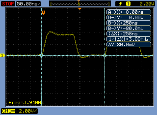
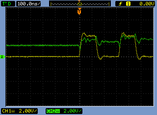
    I did some measurements from oscilloscope the see the signals Clock, CS and MISO (DOUT - ADE7753). As I attached here. I observed in ADE DOUT signal but his wave form don´t sound good. doesn't have an appearance like a wave bit form. yellow line CLOCK SIGNAL and green line ADE DOUT (MISO - MSP430 P1_6).

    Please, do you see anything else to change in the code?

     /* ****   MSP430G2553 SPI PIN definitions **
     *  MOSI - P1.7 (Energia Pin 15)
     *  MISO - P1.6  (Energia Pin 14)
     *  SCL/CS  - P2.0 (Energia Pin 8)
     *  SCLK  - P1.5 (Energia Pin 7)
     */
     
    //Pin declarations Sensor and correlated at MSP430G2
    #define DATAOUT 15//MOSI - 20 DIN - MOD. ADE7753 - VERDE 
    #define DATAIN  14//MISO - 19 DOUT - MOD. ADE7753 - AMARELO
    #define SPICLOCK  7//sck - 18 - MOD. ADE7753 - LARANJA
    #define SLAVESELECT 8// chipSelect - 17 MOD. ADE7753 - AZUL
    
    // transmite um caracter pela interface serial with shift register controller
    unsigned char spi_transfer(unsigned char data)
    {
        long rcvd_data =0;
        while (!(IFG2&UCB0TXIFG)) /*EMPTY*/;   // Wait for TXBUF to be empty
        UCB0TXBUF = data;     
        while (!(IFG2&UCB0RXIFG)) /*EMPTY*/;  // Wait for RXBUF to be full
        rcvd_data = UCB0RXBUF;
        return(rcvd_data);
        //digitalWrite(SLAVESELECT,HIGH);
    }
    
    void setup()
    {
        // put your setup code here, to run once:
        Serial.begin(9600);
         // start the SPI library:
        SPI.begin(); /* Initialize SPI */
        SPI.setDataMode(SPI_MODE1); // CPOL =0 and CPHA =0 
        SPI.setClockDivider(4); // the command is to use SPI =  or 4 MHz,DIV4 = 3,91MHZ , DIV5 = 3,13MHZ
        SPI.setBitOrder(LSBFIRST); // I have tested LSB and MSBFirst.
        pinMode(SLAVESELECT, OUTPUT);
        digitalWrite(SLAVESELECT, HIGH);  
        pinMode(DATAOUT, OUTPUT);
        pinMode(DATAIN, INPUT);
        // configuring interruption of the serial interface (reception)
        IFG2 &= ~UCA0RXIFG;   // clear the Serial Interrupt RX flag
        //IFG2 &= ~UCA0TXIFG;   // clear the Serial Interrupt TX flag
        delay(500);
    }
    
    long read_ADE7753MEM(int ADE7753_MEM_address, int bytes_to_read)
    {
      //Serial.print("Multi-readddr>");
      //Serial.print(EEPROM_address, HEX);
      //Serial.println(" Data starts:");
      long data = 0;
      byte reader_buf = 0;
      //byteRead =0;
      digitalWrite(SLAVESELECT,LOW);
      spi_transfer((char)(ADE7753_MEM_address));      //LSByte Register address
         // here there should be a t9 delay
      delay(68); // to keep t9 - Minimum time between read command considering Clock at 16 Mhz - Min Delay (64)
      for (int i = 0; i < bytes_to_read; i++){
      delay(4); //yo keep t8 - Minimum time between data byte transfers during a multibyte read - Min Delay (0,806)
      reader_buf = spi_transfer(0x00); //get data byte
    
        data = data|reader_buf;
        if (i< bytes_to_read) {
          data = data<<8;
        }
    }
      digitalWrite(SLAVESELECT,HIGH); //release chip, signal end transfer
      return data;
    }
    
    void loop()
    {
       ADE7753_output_data = read_ADE7753MEM(VRMS,3);
       Serial.println("STATUS VRMS");
       Serial.println(ADE7753_output_data, BIN);
       Serial.println(ADE7753_output_data, HEX);
       delay(1000);
    }


    CLOCK AND 1ADE7753 DOUT MEASUREMENTs

    To keep the clock value DIV4

    CLOCK SIGNAL (YELLOW) AND DOUT / MISO_P1_6 GREEN (FROM ADE7753 / MSP430)

  • The CLK signal looks adequate, but the MISO signal shows signs of bus conflict. If you're using a Launchpad: Did you remove the P1.6 (LED) jumper?

    Reading data sheet Fig 94, I'm pretty sure bytes are sent/received MSBFIRST.

    I suggest you try reading a register with a known (non-0) value. Maybe MODE (0x09)=0x000C or something.

    More generally: This is a 5V device. How are you connecting it to the MSP430 (3.3V)? And how are you providing CLKIN?

  • Hi Bruce, thanks. I write the answer to your questions bellow:

    1. I had remove the P1.6 (led) jumper.

    2. I had the same understanding about MSBFIRST.

    3. You have a genial idea, I'll do it and let you know soon.

    4. I using the 33K resistor to connect DOUT from ADE7753 to MISO from MSP430g2553. I'll buy one LVTTL bidirecional converter to include on my tests.

    5. I using 2 capacitors and 1 XTAL connected in the ADE PIN 15 and 16. I have doubts about If is necessary to use PIN 14 (IRQ PIN). 

    I have understanding that the IRQ PIn need to connect to access specific registers.

    I'll try to make more tests tomorrow!

    Thanks a lot for your assistance!

    BR,

    Alex

  • Hi Bruce,

    I have success when I include LVL TTL converter base on BSS138!

    Thanks a lot for your assistance!

    BR

    Alex

**Attention** This is a public forum