This thread has been locked.

If you have a related question, please click the "Ask a related question" button in the top right corner. The newly created question will be automatically linked to this question.

CCS/MSP432P401R: MICROCONTROLLER WITH MAXIMUM PERFORMANCE

Part Number: MSP432P401R

Tool/software: Code Composer Studio

Hello everyone, I hope and you are so kind to help me with a question.

I was testing with the MSP432p401r, I set the DCO source and MCLK and SMCLK signals to a frequency of 48MHz. After setting it up I used only one XOR instruction within a while loop, hoping to get a 24MHZ frequency as a result, however , the frequency I get is 1 MHz.

I observed through the P4.3 and P7.0 pins (configured in their primary function) the MCLK and SMLK signals, and they are effectively 48 MHZ.

My question is:
Why if the DCO clock source is set to 48 MHz, and the MCLK and SMCLK signals are powered by the DCO source, without pre-scaler, does the program execute a single XOR instruction at 1 MHZ?

thanks: D

My code:

#include "msp.h"
#include "driverlib.h"

void main(void)
{
	
	MAP_PCM_setCoreVoltageLevel(PCM_VCORE1);
	MAP_PCM_setPowerState(PCM_AM_LDO_VCORE1);

	MAP_FlashCtl_setWaitState(FLASH_BANK0, 2);
	MAP_FlashCtl_setWaitState(FLASH_BANK1, 2);

	MAP_CS_setDCOCenteredFrequency(CS_DCO_FREQUENCY_48);
	MAP_CS_initClockSignal(CS_MCLK,CS_DCOCLK_SELECT,CS_CLOCK_DIVIDER_1);					 
	MAP_CS_initClockSignal(CS_SMCLK,CS_DCOCLK_SELECT,CS_CLOCK_DIVIDER_1);					 	
	MAP_CS_enableClockRequest(CS_MCLK);
	MAP_CS_enableClockRequest(CS_SMCLK);


	WDTCTL = WDTPW | WDTHOLD;
	
	P4DIR |= BIT3;
	P4OUT &= ~BIT3;
	P4SEL0 |= BIT3;
	P4SEL1 &= ~BIT3;

	P7DIR |= BIT0;
	P7OUT &= ~BIT0;
	P7SEL0 |= BIT0;
	P7SEL1 &= ~BIT0;

	P1DIR |= BIT0;

	while(1){
		P1OUT ^=BIT0;
	}
}

  • Hi,

    It is not a XOR instruction.

    It is 

        while(1){
            P1OUT ^=BIT0;
        }
    First, arm will take more cycles to run an instruction than MSP430. 
    Second, it includes a while loop besides XOR instruction.
    Third, It is a C language, not assembly code.
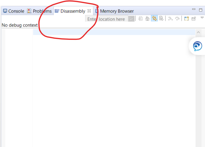
    My advice is that you can see the assembly code under debug mode:
      
  • Current recommendations are that you only need one wait state.

  • JUAN DOMINGUEZ said:

    Part Number: MSP432P401R

    Tool/software: Code Composer Studio

    Hello everyone, I hope and you are so kind to help me with a question.

    I was testing with the MSP432p401r, I set the DCO source and MCLK and SMCLK signals to a frequency of 48MHz. After setting it up I used only one XOR instruction within a while loop, hoping to get a 24MHZ frequency as a result, however , the frequency I get is 1 MHz.

    I observed through the P4.3 and P7.0 pins (configured in their primary function) the MCLK and SMLK signals, and they are effectively 48 MHZ.

    My question is:
    Why if the DCO clock source is set to 48 MHz, and the MCLK and SMCLK signals are powered by the DCO source, without pre-scaler, does the program execute a single XOR instruction at 1 MHZ?

    You should write code in assembler to make things completely clear.

    By the way, I am using Cortex-M0+ with 100MHz MCLK (down to 1.7V) that can do pin XOR (without loop, executed from flash) in one CPU cycle. Without voltage core levels and wait states configuration.

  • Hi,

    True, I skipped the WHILE (1) loop, and was confused, thinking as if the ARM were executing the instructions just like the MSP430.

    I also didn't know that I could see the code in assembler, that was very helpful, I checked the Cortex-M4F datasheet to see the clock cycles needed to execute each instruction shown in DISSASEMBLY window (corresponding to WHILE cycle and P1OUT ^ = BIT0), and indeed, the total cycles necessary to execute those instructions approximately coincided with the generated frequency.

    Thanks, I was a little confused.

    Tampoco sabía que podía ver el código en ensamblador, eso fue muy útil, revisé la hoja de datos del Cortex-M4F para ver los ciclos de reloj necesarios para ejecutar cada instrucción mostrada en la ventana DISSASEMBLY (correspondientes al ciclo WHILE y al P1OUT^=BIT0), y efectivamente, los ciclos necesarios totales para ejecutar esas instrucciones coincidieron aproximadamente con la frecuencia generada.

  • JUAN DOMINGUEZ said:

    True, I skipped the WHILE (1) loop, and was confused, thinking as if the ARM were executing the instructions just like the MSP430.

    But MSP430x5xx/6xx (without FRAM wait states) port write will take 2 cycles, xor 1 cycle, and write back 3 cycles. That is total of 6 CPU cycles without loop.

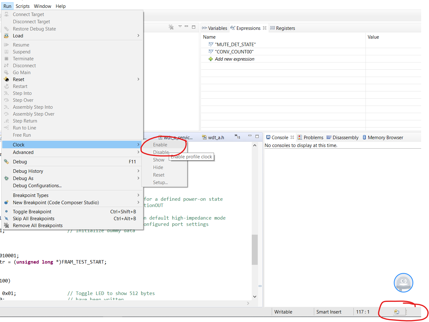
  • Add one way to count the cycle, you can enable the clock and can see the CPU cycles used in the CCS.

**Attention** This is a public forum