Hello,
I'am writing code for my thesis using MSP430F67641 on self designed board.
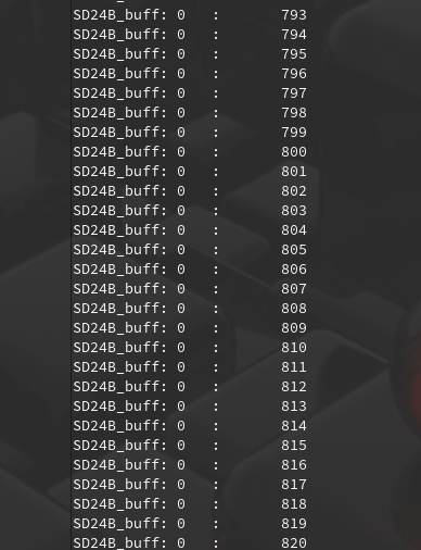
I need to set up Sigma-delta module for measuring mains AC voltage but i allways read a 0 value from the conversion memory register.
Sometimes i was able to catch some random data from the SD24 memory register so i'm quite sure that there is some software mistake,
Everything besides SD24 module works fine.
SD is clocked by SMCLK ( 16MHz ) devided by 16 to pass maximum requrements for selected uC.
here is the code:
#include <msp430.h>
#include <inttypes.h>
#include <stdio.h>

void CLOCKinit(void);
void GPIOinit(void);
void USCIinit(void);
void TIMERinit(void);
void LEDseq(void);
void SD24Binit(void);
void USCI_send_string(char*);
void USCI_send_char(char);


unsigned long SD24B_result = 0; //Sigma - delta
unsigned long SD24B_result_2 = 0; //Sigma - delta
long counter = 0;
int main(void)
{
    	WDTCTL = WDTPW | WDTHOLD;               // Stop watchdog timer
	CLOCKinit();
        GPIOinit();
	TIMERinit();
	USCIinit();
	SD24Binit();

	_bis_SR_register(GIE);			// Global interrupt enable

	char buffer[32];

    	for(;;)
	{
		SD24BCCTL0 |= SD24SC;
		sprintf(buffer, "SD24B_buff: %ld\t:\t%ld\n\r", SD24B_result, counter);
		USCI_send_string(&buffer[0]);
		for (long i=0 ; i<200000 ; i++) {};
		LEDseq();

    	}
   	return 0;
}

void CLOCKinit(void)
{
	UCSCTL1 = DCORSEL_4;
	UCSCTL3 = SELREF__REFOCLK;	//FLL reference clock -> REFO (32,768 KHz)
	UCSCTL2 = 0x0000;
        UCSCTL2 |= 487 | FLLD__1;			//FLLN = 487 / FLLD = 2;
	UCSCTL4 = SELS__DCOCLK | SELM__DCOCLK;
}

void LEDseq(void)
{
	static unsigned short shift = 0;
	if (shift < 2) shift++;
	else
	{
		shift = 0;
	}
	P4OUT = P4OUT | (0x07);
	P4OUT &= ~(1<<shift);
}

void GPIOinit(void)
{
	P2DIR |= BIT3;
	P4DIR |= 0x0F;                          // Set P1.0 to output direction
	P4OUT = 0x000F;
	P4OUT = ~(0x0F);
}

void TIMERinit(void)
{
	TA0CTL |= TASSEL__SMCLK | ID__1 | MC__UP | TAIE;
	TA0CCR0 = 16000 - 1;
	TA0CCTL0 |= CCIE;
}

void USCIinit(void)
{
	//UART MODULE CONFIG
	UCA2CTL1 = UCSWRST | UCSSEL__SMCLK;

	//BAUD 19200
	UCA2BRW = 833;
	UCA2MCTLW = UCBRS2_H;

	// IO PORT CONFIG
	// P2.2 -> RXD input
	// P2.3 -> TXD output
	P2SEL = BIT2 | BIT3;

	UCA2CTL1 &= ~UCSWRST;
}

void SD24Binit(void)
{
	// Clock source = SMCLK
	// Clock source divide / 16
	// Internal reference
	SD24BCTL0 = SD24PDIV_4 ;
	SD24BCTL0 |= SD24SSEL__SMCLK;
	SD24BCTL0 |= SD24REFS;
	SD24BIE = SD24IE0;
	SD24BCCTL0 = SD24SNGL;
	__delay_cycles(0x3600);
}
void USCI_send_string(char *buffer)
{
	while (*buffer)
	{
		USCI_send_char(*buffer++);
	}
}

void USCI_send_char(char char_to_send)
{

	UCA2TXBUF = char_to_send ;
	while (UCA2STATW & UCBUSY);
}

void __attribute__((interrupt(TIMER0_A0_VECTOR))) TimerA_ISR(void)
{
	TA0CTL &= ~(TAIFG);
}

void __attribute__ ((interrupt(SD24B_VECTOR))) SD24BISR (void)
{
    switch (SD24BIV)
    {
        case SD24BIV_SD24OVIFG:             // SD24MEM Overflow
            break;
        case SD24BIV_SD24TRGIFG:            // SD24 Trigger IFG
            break;
        case SD24BIV_SD24IFG0:              // SD24MEM0 IFG
		SD24B_result = (SD24BMEMH0);
		SD24B_result = (SD24B_result<<16) | SD24BMEML0;
    		counter++;
            break;
        case SD24BIV_SD24IFG1:              // SD24MEM1 IFG
            break;
        case SD24BIV_SD24IFG2:              // SD24MEM2 IFG
            break;
    }
}

Board schematic (based on TIDM-THDREADING reference design):
Could you help me resolve this?