Because of the holidays, TI E2E™ design support forum responses will be delayed from Dec. 25 through Jan. 2. Thank you for your patience.

This thread has been locked.

If you have a related question, please click the "Ask a related question" button in the top right corner. The newly created question will be automatically linked to this question.

MSP430FR6047: Using on board ezFET emulator for programming other MCUs?

Part Number: MSP430FR6047
Other Parts Discussed in Thread: EVM430-FR6047, MSP-FET

Hello friends,

These days I starting working on a new project based on another TI's devices. This time one its MSP430 low power MCUs for a sensing project. MSP430FR6047.

I took a look at the page on device on TI website and even saw EVM430-FR6047 and related files.

Before this i used to work with TI's DSPs such as C2000 and C6000 and Hercules MCUs and I have had XDS560v2 and XDS100v2 for programming, debugging and so on. Everthing was well and no issues.

But now I want to know that:

1- To program and debug MSP430 MCU families there should be another programmer other than XDS560v2 and XDS100v2 availabe on this link.  However Luckily there is another chiper solution which TI names it ezFET Lite and the description is here. I saw that, this solution availabe on EVM430-FR6047.  Therefore I am now curious to know why there is a 14 pin JTAG connector on this evaluation module while it has an on-board ezFET lite opportunity? 

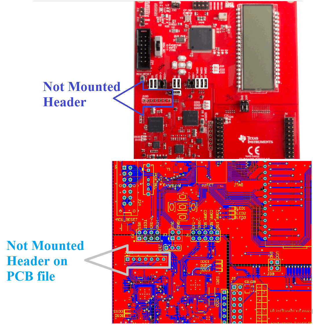
2-As you see in the image below there is a header J100 which is not mounted on board. I think I can use this part to program and debug othe MSP430 MCUs. In fact it can play the role of a MSP programmer. Did anybody do so yet?

Thanks and regards,
Hossein

  • Hello,

    Yes, you can use the onboard eZ-FET debugger to program other MSP430 devices over SBW. You may not even need to solder the header on J100 to do so. The JTAG SBW pins are available on J2 header - just remove the jumpers. VCC and GND should be available from other headers. You can learn more about the eZ-FET in the MSP Debuggers user's guide.

    Hossein Forouzani said:
    Therefore I am now curious to know why there is a 14 pin JTAG connector on this evaluation module while it has an on-board ezFET lite opportunity? 

    This connector allows the more advanced MSP-FET to program and debug the device over 4-wire JTAG or BSL.

    Regards,

    James

  • Hello,

    James Evans said:

    This connector allows the more advanced MSP-FET to program and debug the device over 4-wire JTAG or BSL.

    Would you mention some of these features. Any related links or documents?
    I want to know if the programming and debugging capabilities missed without using a programmer is critical or not?
    Currently I just want to program the MSP430FR6047 device and don't need advanced debugging features.

    Regards,
    Hossein

  • and another matter,

    I don't want to solder the LCD suggested in the BOM, 'FH-1138P' from ADKOM.
    What other part number do you recommend?

  • Hossein Forouzani said:
    Would you mention some of these features. Any related links or documents?
    I want to know if the programming and debugging capabilities missed without using a programmer is critical or not?

    The MSP Debuggers user's guide is a good resource since it covers these features. You can learn more about the bootstrap loader (BSL) here.

    Hossein Forouzani said:
    Currently I just want to program the MSP430FR6047 device and don't need advanced debugging features.

    You can use the onboard eZ-FET debugger for that assuming the JTAG/SBW circuitry of the target device match the recommendations found in the MSP430 Hardware Tools User's Guide.

    Regards,

    James

**Attention** This is a public forum