


Tool/software: Code Composer Studio
MSP430FR2355
Code Composer Studio
Version: 8.3.1.00004
Slave: MPU6050 ( Accel / Gyro) module
I can Init the MPU6050 no problem.
But when I get to the data gathering ( TX and RX portion), it expected to see the
Master: I2C as TX
TX ADDRESS + Code + RESTART or STOP ( 0x68 + 0x3B + S)
Master:I2C as RX
TX ADDRESS, expect a 1 Byte Response then NACK. (0x68 || data Byte || NACK) Then master expect to acknowledge with a NACK to end transmission
this is suppose to repeat;
What I get is
TX ADDRESS + Stop ( 0x68 + S)
RX ADDRESS || 0x00 + 0x00 || NACK
example below from logic analyser
Really do not know why this is occurring why the master MSP430FR2355 is Transmitting the address only but not the data?
tried putting delays at various location, tried different clock speeds currently set to /8 ( tried from /2 to /20 no luck)

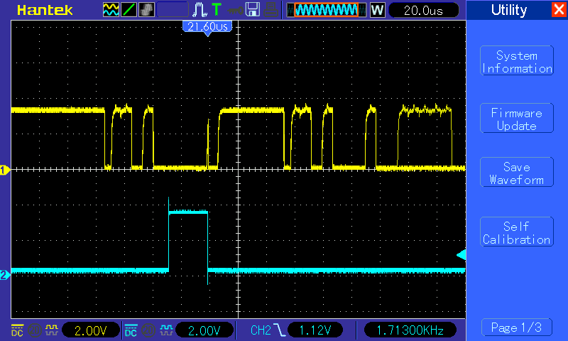
this is the Scope trace Yellow is the data line the Blue is P3 BIT4 ( I place a P3 Bit4 to go Hi and Low within the Interrupt routine, it captures this glitch At the address portion of the I2C Protocol
From the Master
#include <msp430fr2355.h>
#include "stdint.h"


/**
 * MPU-6050   I2C = 0x68
 *
 *
 */

void I2C_busy(void);
void delay(void);

const unsigned int MPU_address = 0x68;  // MPU-6050 i2c  Address

const unsigned int Accel_Xout_H = 0x003B;
const unsigned int Accel_Xout_L = 0x003C;
const unsigned int Accel_Yout_H = 0x003D;
const unsigned int Accel_Yout_L = 0x003E;
const unsigned int Accel_Zout_H = 0x003F;
const unsigned int Accel_Zout_L = 0x0040;

const unsigned int Gyro_Xout_H = 0x0043;
const unsigned int Gyro_Xout_L = 0x0044;
const unsigned int Gyro_Yout_H = 0x0045;
const unsigned int Gyro_Yout_L = 0x0046;
const unsigned int Gyro_Zout_H = 0x0047;
const unsigned int Gyro_Zout_L = 0x0048;

unsigned int RXData = 0;
unsigned int TXByteCtr = 0;
unsigned int SlaveFlag = 0;
unsigned int RXcnt = 0;
volatile unsigned int tx_cntr = 0;
volatile unsigned int stop = 0;
volatile unsigned int read = 0;

signed int TXData[] = {0x6B, 0x00, 0x1A, 0x04, 0x1B, 0x00, 0x1C, 0x00};
unsigned int RX[4];
unsigned int RX1[0x0100];
unsigned int RX1cnt = 0;
signed int x_acc = 0;
signed int y_acc = 0;
signed int z_acc = 0;
signed int x_gyr = 0;
signed int y_gyr = 0;
signed int z_gyr = 0;
unsigned int valid = 0;
signed int acc_led = 0;


int main(void)
{
	WDTCTL = WDTPW | WDTHOLD;	// stop watchdog timer

    P1SEL0 |= BIT2 | BIT3;                  // I2C pins
    P5DIR |= BIT0 | BIT1 | BIT2 | BIT3 | BIT4;   // Stepper driver 0=DIR, 1=STEP, 3-4-5 step value
    P5OUT = 0x00;
    P3DIR = 0xFF;
    P3OUT = 0x00;
    // Disable the GPIO power-on default high-impedance mode to activate
    // previously configured port settings
    PM5CTL0 &= ~LOCKLPM5;

    // Configure USCI_B0 for I2C mode
    UCB0CTLW0 |= UCSWRST;                   // Software reset enabled
    UCB0CTLW0 |= UCMODE_3 | UCMST | UCSYNC; // I2C mode, Master mode, sync
    UCB0CTLW1 |= UCASTP_0;                  // NO Automatic stop generated
                                            // after UCB0TBCNT is reached
    UCB0BRW = 0x0008;                       // baudrate = SMCLK / 8      ------------> 32
    UCB0TBCNT = 0x0000;                     // byte cntr disabled
    UCB0I2CSA = MPU_address;                // Slave address of MPU-6050
    UCB0CTL1 &= ~UCSWRST;
    UCB0IE |= UCRXIE | UCTXIE0 | UCNACKIE | UCTXSTP;  // EN INT TX, RX, NACK

   __bis_SR_register(GIE);             // enable interrupt

   while (UCB0CTLW0 & UCTXSTP);        // Ensure stop condition got sent
   I2C_busy();

   tx_cntr = 0x00;
   TXByteCtr = 0x02;
   UCB0CTLW0 |= UCTR | UCTXSTT;        // TX  0x6B 0x00
   I2C_busy();

   TXByteCtr = 0x02;
   UCB0CTLW0 |= UCTR | UCTXSTT;        // TX 0x1A 0x00
   I2C_busy();

   TXByteCtr = 0x02;
   UCB0CTLW0 |= UCTR | UCTXSTT;        // TX 0x1B 0x00
   I2C_busy();

   TXByteCtr = 0x02;
   UCB0CTLW0 |= UCTR | UCTXSTT;        // TX 0x1C 0x00
   I2C_busy();
/*
 *  MPU6050 init completed
 */

    tx_cntr = 0x0000;
    TXData[0] = 0x3B;
    TXData[1] = 0x3C;
    TXData[2] = 0x3D;
    TXData[3] = 0x3E;
    TXData[4] = 0x3F;
    TXData[5] = 0x40;

    TXData[6] = 0x00;
    TXData[7] = 0x00;
    RXcnt = 0x00;

       // RX data
       // Master    |S|AD+W|   |RA|   |S|AD+R|   |    |ack|
       // Slave            |ack|  |ack| |    |ack|Data|   |
     while (UCB0CTLW0 & UCTXSTP);                      // Ensure stop condition got sent
     I2C_busy();

     while(1)
     {
         P3OUT = 0x00;
            tx_cntr = 0x00;
            TXByteCtr = 0x01;
//            UCB0CTLW0 |= UCSWRST;                   // Software reset enabled
            UCB0CTLW0 |= UCTR;        //  inTX mode
            UCB0CTLW1 |= UCASTP0;
 //           UCB0TBCNT = 0x03;  // tx 2 bytes
//            UCB0CTLW0 &= ~UCSWRST;                   // Software reset enabled
            UCB0CTLW0 |= UCTXSTT;        // I2C start condition
            I2C_busy();
        P3OUT |= BIT0;


 //          UCB0CTLW0 |= UCSWRST;                   // Software reset enabled
            UCB0CTLW0 &= ~UCTR ;          // Receive Mode
            UCB0CTLW1 |= UCASTP1;
            UCB0TBCNT = 0x01;  // rx 1 bytes
//            UCB0CTLW0 &= ~UCSWRST;                   // Software reset enabled

            UCB0CTLW0 |= UCTXSTT;        // I2C start condition inTX mode
            I2C_busy();
            while(read)  __no_operation();
       P3OUT |= BIT1;
            if(valid)
            {
                RX1[RX1cnt++] = x_acc;
                if(RX1cnt > 0x00FF) RX1cnt = 0x0000;
                acc_led = x_acc >>8;
//                P3OUT = acc_led;  // like to see the results in real time

                if(acc_led > 128)
                  {
                      P5OUT |= BIT0;
                      P5OUT |= BIT1;
                      delay();  // stepper motor delay pulse just too fast
                      P5OUT &= BIT1;
                      delay();  // stepper motor delay pulse just too fast
                  }
                  else if (z_gyr < -128)
                  {
                      P5OUT &= ~BIT0;
                      P5OUT |= BIT1;
                      delay();  // stepper motor delay pulse just too fast
                      P5OUT &= BIT1;
                      delay();  // stepper motor delay pulse just too fast
                  }
                P3OUT |= BIT2;
            }
       }
}

void I2C_busy(void)
{
    unsigned int wait;
    while (UCB0STATW & UCBBUSY)
    {
         for(wait = 0xFFFF; wait == 0; wait--)__no_operation();
    }


}

void delay(void)
{
    unsigned int stepper_pulse_delay;
    for(stepper_pulse_delay = 0xFFFF; stepper_pulse_delay == 0; stepper_pulse_delay--) __no_operation();
}


#pragma vector = USCI_B0_VECTOR
__interrupt void USCIB0_ISR(void)
{

    volatile unsigned int I2C_int;
    I2C_int = UCB0IV;

    if(I2C_int == UCIV__UCTXIFG0)  // TX buffer is empty
    {
        if (TXByteCtr)                                // Check TX byte counter
           {
      P3OUT |= BIT4;
            TXByteCtr--;
            UCB0TXBUF = TXData[tx_cntr];            // Load TX buffer
            tx_cntr++;
            stop = 0x01;                                // Decrement TX byte counter
      P3OUT &= ~BIT4;
           }
        else
           {
            stop = 0x00;
            UCB0CTLW0 |= UCTXSTP;                     // I2C stop condition
           }

    }
    else if(I2C_int == UCIV__UCRXIFG0)  // RX data present
    {
        UCB0CTLW0 |= UCTXSTP;
        RXData = UCB0RXBUF;
        RX[RXcnt] = RXData;
        RXcnt++;
        if(RXcnt > 0x0001)
        {
            RXcnt = 0;
            x_acc = RX[1] | (RX[0]<<8);
            valid = 0x0001;
        }
        valid = 0x0001;
        read = 0x0000;
   P3OUT |= BIT5;
    }
    else if(I2C_int == UCIV__UCNACKIFG)  //  NACK received
    {
        stop = 0x00;
        read = 0x0000;
        UCB0CTLW0 |= UCTXSTP;                     // I2C stop condition
    }
    else if(I2C_int == UCIV__UCSTPIFG )  // Stop received
    {
        stop = 0x00;
    }
}
