This thread has been locked.

If you have a related question, please click the "Ask a related question" button in the top right corner. The newly created question will be automatically linked to this question.

MSP430F5659: Halt RTC operation after controller power off even with VBat present

Part Number: MSP430F5659


Hi Team,

We are referring to RTC battery application note https://www.ti.com/lit/an/slaa665b/slaa665b.pdf and source code www.ti.com/lit/zip/slaa665.

As per reference code www.ti.com/lit/zip/slaa665, source code performs:

  • Check if RTC backup supply was drained or not.
    • If drained reset RTC time.
    • If not retain RTC values.
  • in continuous application loop(While(1)):
    • Enter into low power mode 3 and enable global interrupt
    • On exit from low power mode due to RTC interrupt:
    • Check RTC Oscillator fault,
      • if RTC oscillator fault occurred, then reset RTC time and perform other operations related to oscillator fault.
      • If no oscillator fault, then Print/ send current time value from global time variable(which was updated in RTC ISR) to UART port.

  • RTC ISR:
    • On RTC second interrupt:
      • Toggle GPIO
      • load current time value to global time variable.
      • Exit from controller low power mode 3.
    • On oscillator fault:
      • disable RTC_B_OSCILLATOR_FAULT_INTERRUPT.
      • Exit from controller low power mode 3.

From above sample code we observed RTC continuous update even after supply removed to controller.

That is RTC operation working properly even after controller power off.

The above reference test code has application with low power mode scenario.

As in our product application always be in normal power.
Then we tried with some following changes in reference test:

while(1)

{

//__bis_SR_register(LPM3_bits + GIE);
__bis_SR_register(GIE);
__no_operation();

Where we disabled low power mode entry and enabled only global interrupt.

With above changes we observed that, After controller power OFF RTC time values are not being updated, As on power ON observed same RTC time values as same before power OFF.

As per reference to https://www.ti.com/lit/an/slaa665b/slaa665b.pdf:

  • On Reset LOCKBAK after RTC configuration, RTC values should operate normally even there is no Vcc or LMPx.5 mode.

After above exercise, it seems to be that after controller power OFF RTC time values getting updated, only if controller was in LPM3.

Please do suggest us if anything missing from our end.

  • Hi,

    You just modified this one  code(do not enter the LPM3 mode), and deleted the program that exit  LPM3.5 mode in the RTC interrupt, and then the RTC value was not updated, right?

    Best Regards

    Johnson

  • Hi Johnson,

    Thanks for your response!!!

    Yes, your right.

    The main intention for above mentioned modification, controller not to operate in low power mode during normal execution(application execution) and RTC values should get update even when controller powered OFF.

    Looking forward for your response and hopefully we resolve issue as soon as possible.

    Regards,

    Satyanarayan G.

  • Hi,

    I test this issue you described, and the result show that the RTC function is normal.

    Some note need to be attention:
    When you disable LPM3 mode, The while(1) program will continue to run, which may be the cause of the problem, so you need to move the program in while(1) to the interrupt service routine, 

    Attach my test code :

    /* --COPYRIGHT--,BSD
     * Copyright (c) 2015, Texas Instruments Incorporated
     * All rights reserved.
     *
     * Redistribution and use in source and binary forms, with or without
     * modification, are permitted provided that the following conditions
     * are met:
     *
     * *  Redistributions of source code must retain the above copyright
     *    notice, this list of conditions and the following disclaimer.
     *
     * *  Redistributions in binary form must reproduce the above copyright
     *    notice, this list of conditions and the following disclaimer in the
     *    documentation and/or other materials provided with the distribution.
     *
     * *  Neither the name of Texas Instruments Incorporated nor the names of
     *    its contributors may be used to endorse or promote products derived
     *    from this software without specific prior written permission.
     *
     * THIS SOFTWARE IS PROVIDED BY THE COPYRIGHT HOLDERS AND CONTRIBUTORS "AS IS"
     * AND ANY EXPRESS OR IMPLIED WARRANTIES, INCLUDING, BUT NOT LIMITED TO,
     * THE IMPLIED WARRANTIES OF MERCHANTABILITY AND FITNESS FOR A PARTICULAR
     * PURPOSE ARE DISCLAIMED. IN NO EVENT SHALL THE COPYRIGHT OWNER OR
     * CONTRIBUTORS BE LIABLE FOR ANY DIRECT, INDIRECT, INCIDENTAL, SPECIAL,
     * EXEMPLARY, OR CONSEQUENTIAL DAMAGES (INCLUDING, BUT NOT LIMITED TO,
     * PROCUREMENT OF SUBSTITUTE GOODS OR SERVICES; LOSS OF USE, DATA, OR PROFITS;
     * OR BUSINESS INTERRUPTION) HOWEVER CAUSED AND ON ANY THEORY OF LIABILITY,
     * WHETHER IN CONTRACT, STRICT LIABILITY, OR TORT (INCLUDING NEGLIGENCE OR
     * OTHERWISE) ARISING IN ANY WAY OUT OF THE USE OF THIS SOFTWARE,
     * EVEN IF ADVISED OF THE POSSIBILITY OF SUCH DAMAGE.
     * --/COPYRIGHT--*/
    /**********************************************************************
     *
     * RTC_B_with_Backup.c
     *
     * This program demonstrates proper usage of RTC_B with Battery Backup on
     * F66xx family devices. The code distinguishes between a BOR event, and
     * a VBAT switching event, to determine if the RTC calendar registers
     * should contain accurate time information and initialize the RTC
     * accordingly.
     *
     * Time information is relayed to the Demo_Host F5529 Launchpad over UART
     * to be passed back to the PC and viewed by the user. This shows that
     * time is retained if VBAT is present, and is lost if VBAT becomes
     * drained.
     *
     **********************************************************************/
    
    #include "driverlib.h"
    #include "UART.h"
    
    volatile Calendar newTime;
    Calendar currentTime;
    
    //P2.0 = TXD, P2.1 = RXD
    const uint8_t port_mapping[] = {
        //Port P2:
        PM_UCA0TXD,
        PM_UCA0RXD,
        PM_NONE,
        PM_NONE,
        PM_NONE,
        PM_NONE,
        PM_NONE,
        PM_NONE
    };
    
    //strings to send to host to display switching/reset detection
    #define TIME_LOST_STRING_LENGTH 30
    #define TIME_RETAINED_STRING_LENGTH 37
    #define OSC_FAULT_STRING_LENGTH 35
    
    const unsigned char timeLostString[TIME_LOST_STRING_LENGTH] = 			"Reset event. Time was reset.\r\n";
    const unsigned char timeRetainedString[TIME_RETAINED_STRING_LENGTH] = 	"Switching event. Time was retained.\r\n";
    const unsigned char oscFaultString[OSC_FAULT_STRING_LENGTH] = 			"Oscillator Fault. Time was reset.\r\n";
    
    unsigned char oscFault = 0;
    
    void resetTime(void);
    void clearOscFault(void);
    
    void main(void) {
    	unsigned char timeLost;
    
        WDT_A_hold(WDT_A_BASE);	//stop the watchdog
    
        PMM_setVCore( PMM_CORE_LEVEL_3); //change this VCORE to test with different levels/settings
    
        //We have to re-init some crystal and RTC settings before clearing LOCKBAK so that crystal/RTC won't stop if we're coming out of VBat
        //init crystal
    	UCSCTL6 = XT1DRIVE_3 | XCAP_3;	//set up the crystal load capacitors for 12pF
    	//init RTC
    	RTCCTL01 |= RTCBCD;		//use RTC in BCD mode
    	RTCCTL01 &= ~RTCHOLD; //keep RTC running when we clear LOCKBAK
    
        //erase LOCKBAK bit for crystal + RTC settings to take effect
    	//you must erase LOCKBACK or you won't be able to check RTC flag etc
        while(BAKCTL & LOCKBAK)
        {
        	BAKCTL &= ~(LOCKBAK);
        }
    
        //check if backup supply was drained or not by checking BAKMEM0, RTCOFIFG, and RTCCALS
        //BAKMEM0 we are checking for backup memory retention
        //RTCOFIFG we are checking if an oscillator fault occurred while we were on the backup supply
        //RTCCALS will be retained through switching event but cleared on brownout, so also indicates if RTC calendar registers retained
        //NOTE: RTCCTL2 setting and checking should use whatever calibration values are required for the specific device/application. RTCCALS is used as an example in this case.
        if((BAKMEM0 == 0xDEAD) && !(RTCCTL01 & RTCOFIFG) && (RTCCTL2 & RTCCALS)) //backup not lost
        {
        	timeLost = 0; 	//we retained the RTC data
    
            P1DIR |= BIT0;	//RTC LED re-initialize to be output (GPIO are not retained)
        }
        else //either first startup or we lost backup RAM
        {
        	timeLost = 1;
    
            P1OUT &= ~BIT0;
            P1DIR |= BIT0;	//RTC LED
    
            //Clear faults
            clearOscFault();
    
    		//reinitialize the RTC time
            resetTime();
    
            RTCCTL2 |= RTCCALS; //this bit is retained so can be used as a check for VBAT switching
            BAKMEM0 = 0xDEAD; 	//write in the signature
        }
    
        //Enable interrupt for RTC Ready Status, which asserts when the RTC
        //Calendar registers are ready to read.
        RTC_B_clearInterrupt(RTC_B_BASE, RTC_B_CLOCK_READ_READY_INTERRUPT | RTC_B_OSCILLATOR_FAULT_INTERRUPT); //clear flag before enabling interrupt
        RTC_B_enableInterrupt(RTC_B_BASE, RTC_B_CLOCK_READ_READY_INTERRUPT | RTC_B_OSCILLATOR_FAULT_INTERRUPT);	//enable ready interrupt and fault interrupt
        RTC_B_startClock(RTC_B_BASE);	//start clock
    
        //CONFIGURE PORTS- pass the port_mapping array, start @ P2MAP01, initialize
        //a single port, do not allow run-time reconfiguration of port mapping
        PMAP_initPortsParam initPortsParam = {0};
        initPortsParam.portMapping = port_mapping;
        initPortsParam.PxMAPy = (uint8_t  *)&P2MAP01;
        initPortsParam.numberOfPorts = 1;
        initPortsParam.portMapReconfigure = PMAP_DISABLE_RECONFIGURATION;
        PMAP_initPorts(PMAP_CTRL_BASE, &initPortsParam);
    
        P2SEL = BIT0 | BIT1;	//P2.0 = TXD, P2.1 = RXD
    
        //init UART for sending time data
        initUART();
    
        //Enable UART module for operation
        USCI_A_UART_enable(USCI_A0_BASE);
    
        //output whether a reset or a switching event occurred, time lost/retained
        if(timeLost)
        {
        	transmitString((unsigned char*)timeLostString, TIME_LOST_STRING_LENGTH);
        }
        else
        {
        	transmitString((unsigned char*)timeRetainedString, TIME_RETAINED_STRING_LENGTH);
        }
    
        while(1)
        {
    //    	__bis_SR_register(LPM3_bits + GIE);
            __bis_SR_register(GIE);
        	__no_operation();
        }
    }
    
    #if defined(__TI_COMPILER_VERSION__) || defined(__IAR_SYSTEMS_ICC__)
    #pragma vector=RTC_VECTOR
    __interrupt
    #elif defined(__GNUC__)
    __attribute__((interrupt(RTC_VECTOR)))
    #endif
    void RTC_B_ISR(void)
    {
    	 while(BAKCTL & LOCKBAK)                    // Unlock backup system
    	        BAKCTL &= ~(LOCKBAK);
    
    	switch (__even_in_range(RTCIV, 16)) {
    	case 0: break;  //No interrupts
    	case 2: //RTCRDYIFG
    			P1OUT ^= BIT0;	//Toggle P1.0 every second
    			newTime = RTC_B_getCalendarTime(RTC_B_BASE);
    			currentTime = newTime;  //we're buffering the data in case RTC interrupts again while still sending over UART
    			transmitString(calendarToString(currentTime), CALENDAR_STRING_LENGTH);
    //			__bic_SR_register_on_exit(LPM3_bits);
    //			__no_operation();	//put breakpoint here to check on time if desired
    			break;
    	case 4: break;	//RTCEVIFG
    	case 6: break;	//RTCAIFG
    	case 8: break;  //RT0PSIFG
    	case 10: break; //RT1PSIFG
    	case 12: //RTCOFIFG
    		oscFault = 1;
    		RTC_B_disableInterrupt(RTC_B_BASE, RTC_B_OSCILLATOR_FAULT_INTERRUPT); //disable further fault interrupts
    //		__bic_SR_register_on_exit(LPM3_bits); //wake to handle fault
    		//check until fault clears
    		clearOscFault();
    		oscFault = 0;
    
    		//reset time
    		resetTime();
    
    		//print message about osc fault and time resetting
    		transmitString((unsigned char*)oscFaultString, OSC_FAULT_STRING_LENGTH);
    
    		//restart RTC
    		//Enable interrupt for RTC Ready Status, which asserts when the RTC
    		//Calendar registers are ready to read.
    		RTC_B_clearInterrupt(RTC_B_BASE, RTC_B_CLOCK_READ_READY_INTERRUPT | RTC_B_OSCILLATOR_FAULT_INTERRUPT); //clear flag before enabling interrupt
    		RTC_B_enableInterrupt(RTC_B_BASE, RTC_B_CLOCK_READ_READY_INTERRUPT | RTC_B_OSCILLATOR_FAULT_INTERRUPT); //enable ready interrupt and fault interrupt
    		RTC_B_startClock(RTC_B_BASE);   //start clock
    		break;
    	case 14: break; //Reserved
    	case 16: break; //Reserved
    	default: break;
    	}
    }
    
    //reset the time to our starting time
    void resetTime(void)
    {
        //Setup Current Time for Calendar
        currentTime.Seconds = 0x00;
        currentTime.Minutes = 0x30;
        currentTime.Hours = 0x04;
        currentTime.DayOfWeek = 0x01;
        currentTime.DayOfMonth = 0x04;
        currentTime.Month = 0x05;
        currentTime.Year = 0x2015;
    
        RTC_B_initCalendar(RTC_B_BASE,
    		&currentTime,
    		RTC_B_FORMAT_BCD);
    }
    
    //clear oscillator faults
    void clearOscFault(void)
    {
        //Clear OFIFG fault flag
        SFRIFG1 &= ~OFIFG;
        //wait for crystal to stabilize
        while (UCSCTL7 & XT1LFOFFG)
        {
            //Clear OSC flaut Flags fault flags
            UCSCTL7 &= ~(XT1LFOFFG);
    
            //Clear OFIFG fault flag
            SFRIFG1 &= ~OFIFG;
        }
        UCSCTL6 &= ~XT1OFF;
    
        RTC_B_clearInterrupt(RTC_B_BASE, RTC_B_OSCILLATOR_FAULT_INTERRUPT);
    }
    

    Best Regards

    Johnson

  • Hi Johnson,

    Thanks for your details information.

    We will analyze shared code and test with same.

    Some note need to be attention:
    When you disable LPM3 mode, The while(1) program will continue to run, which may be the cause of the problem, so you need to move the program in while(1) to the interrupt service routine,

    - As per your suggestion/ code in wihle(1), performing only enabling global interrupt continuously and printing time values in RTC ISR.

    How can we handle situation where our application need to execute in while(1) not in RTC ISR.

    - We would mention regarding controller, as in our product we are using MSP430F5659 controller.

    Please do confirm on which controller you have tested, so that which can help us to understand further.

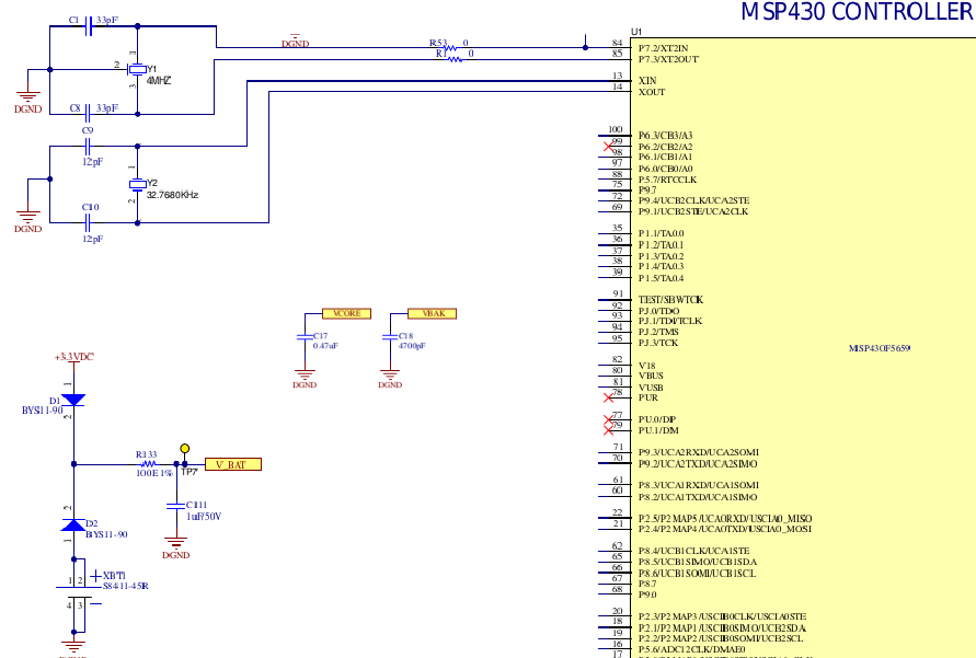
    - Below is schematic for RTC which we are using for our custom board.

    Please do kindly share your comments on above schematic, if we are missing anything.

    Regards,

    Satyanarayan G.

  • Hi,

    I used the F6638 device described in the slaa665b.pdf document for my test, but it seems that the test results should also apply to F5659.
    I took a look at your schematic, it looks normal, you can test it to see if it can solve your problem.

    Best Regards

    Johnson

**Attention** This is a public forum