This thread has been locked.

If you have a related question, please click the "Ask a related question" button in the top right corner. The newly created question will be automatically linked to this question.

CCS/MSP430FR6989: The last byte of data that I transmit never sends.

Part Number: MSP430FR6989

Tool/software: Code Composer Studio

I have implemented automatic baudrate detection on my MSP430. It is working as expected however when I go from reading in the synch frame to transmitting data, the last byte of data that I send never transmits and the byte before that is also sent as a 0xFF.

Something I noticed was that when I enter debug mode everything sends perfectly, however when I just flash my program onto the MSP430 and use an oscilloscope it doesn't send the right data.

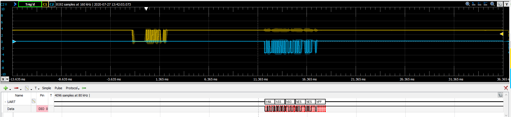
Here is my oscilloscope reading:

Here is the code that I write: 

  LIN_Read_Header();

  LIN_Wait();

  LIN_Send_Data(0x4A);                      //Whatever data you want to sent
  LIN_Send_Data(0x55);
  LIN_Send_Data(0x93);
  LIN_Send_Data(0xE5);
  LIN_Send_Data(0xE5);
  LIN_Send_Data(0xE5);


  LIN_CRC();

void LIN_Send_Data(volatile unsigned char data){
    CRC_SUM=(CRC_SUM+data);                   // Keep a running sum of all the DATA
    CRC_SUM=(CRC_SUM&255)+(CRC_SUM>>8);
   
    while(!(UCA0IFG & UCTXIFG));
    UCA0TXBUF=data;


}
void LIN_CRC(){
    CRC_SUM=(~CRC_SUM) & 255;
    
    while(!(UCA0IFG & UCTXIFG));
    UCA0TXBUF=CRC_SUM;

    CRC_SUM=0;


}

  • I have never tried using the auto baud rate detection system but I suspect that your problem is in that code.

  • Before using auto baud rate everything was sending correctly. The weird thing is that debugging makes the code work, and it doesn't matter if I use the CRC function or the regular send data function, my last byte of data never sends and the byte before it always turns into an 0xFF. My guess is that there is something wrong with the timing since the debug allows more time for the code to send, but the send data function works fine for all the other bytes of data.

  • "Before using auto baud rate everything was sending correctly."

    Which should be a big hint that the autobaud code is the source of the problem. Post it and maybe I will see something obvious.

  • Here is the code:

    //******************************************************************************
    #include <msp430.h>
    #include <stdio.h>
    
    volatile unsigned char RXData = 0;
    volatile unsigned char TXData = 1;
    
    
    volatile unsigned int i=0;
    volatile unsigned int CRC_SUM=0;
    
    int main(void)
    {
    
        WDTCTL = WDTPW | WDTHOLD;                 // stop watchdog
    
      // Configure GPIO
      P1OUT &= ~BIT0;                           // Clear P1.0 output latch
      P1DIR |= BIT0;                            // For LED on P1.0
    
    
      P4SEL0 |= BIT2 | BIT3;                    // Configure UART pins
      P4SEL1 &= ~(BIT2 | BIT3);
    
      PJSEL0 |= BIT4 | BIT5;                    // Configure XT1 pins


      P2OUT &= ~BIT0;
      P2DIR |= BIT0;                    // Configure LIN_EN pin


      // Disable the GPIO power-on default high-impedance mode to activate
      // previously configured port settings
      PM5CTL0 &= ~LOCKLPM5;
    
      // Configure one FRAM waitstate as required by the device datasheet for MCLK
      // operation beyond 8MHz _before_ configuring the clock system.
      FRCTL0 = FRCTLPW | NWAITS_1;
    
      // XT1 Setup
      CSCTL0_H = CSKEY >> 8;                    // Unlock CS registers
      CSCTL1 = DCOFSEL_4|DCORSEL;                       // Set DCO to 16MHz
      CSCTL2 = SELA__LFXTCLK | SELS__DCOCLK | SELM__DCOCLK;
      CSCTL3 = DIVA__1 | DIVS__1 | DIVM__1;     // Set all dividers
    
      CSCTL4 &= ~LFXTOFF;                       // Enable LFXT1
      do
      {
        CSCTL5 &= ~LFXTOFFG;                    // Clear XT1 fault flag
        SFRIFG1 &= ~OFIFG;
      }while (SFRIFG1&OFIFG);                   // Test oscillator fault flag
      CSCTL0_H = 0;                             // Lock CS registers
    
      while(1){
      // Configure USCI_A0 for UART mode
    
      UCA0CTLW0 = UCMODE_3 | UCSWRST | UCSSEL_2 | UCDORM;// | UCBRKIE; // SMCLK source, no interrupts, not dormant, no break, no addr chars, hold in reset, don't put BRK in RXBUF0
    
      UCA0ABCTL= UCABDEN; // Auto baud-rate detect enable
    
    
      UCA0BR0 = 104;//52; //53; //79; // Pre-scaler in UCA0BR[0|1] should be set upon auto-baud rate detection
    
      UCA0BR1 = 0x00;


      UCA0MCTLW = 0xD600 | UCBRF_2 | UCOS16; // Over-sampling enabled


      UCA0CTL1 &= ~UCSWRST; // Release from reset
    
    
      UCA0IE |= UCRXIE; // Enable UART RX interrupts for message processing


      LIN_Read_Header();
    
      LIN_Wait();
    
      LIN_Send_Data(0x4A);                      //Whatever data you want to sent
      LIN_Send_Data(0x55);
      LIN_Send_Data(0x93);
      LIN_Send_Data(0xE5);
      LIN_Send_Data(0xE5);
      LIN_Send_Data(0xE5);
    
    
      LIN_CRC();
      }
    }


    void LIN_WakeUp(){
        P1OUT |= BIT0;
        P2OUT |= BIT0;
    
    }
    
    void LIN_Sleep(volatile unsigned int time){
        P1OUT &= ~BIT0;
        P2OUT &= ~BIT0;
    
    }
    
    void LIN_Wait(){
        volatile unsigned int i=0;
    
        P1OUT |= BIT0;
    
        while(!(UCA0IFG & UCTXIFG));


        i=1000000;
        do i--;
        while (i!=0);
    
        P1OUT &= ~BIT0;
    
    }
    
    
    void LIN_Send_Data(volatile unsigned char data){
        CRC_SUM=(CRC_SUM+data);                   // Keep a running sum of all the DATA
        CRC_SUM=(CRC_SUM&255)+(CRC_SUM>>8);
       
        while(!(UCA0IFG & UCTXIFG));
        UCA0TXBUF=data;
    
    
    }
    
    void LIN_CRC(){
        CRC_SUM=(~CRC_SUM) & 255;
        
        while(!(UCA0IFG & UCTXIFG));
        UCA0TXBUF=CRC_SUM;
    
        CRC_SUM=0;
    
    
    }
    
    
    int parity_bit (unsigned int x, unsigned int bits){
        unsigned int count=0;
        unsigned int i=0;
        unsigned int b=1;
    
        for (i=0; i<bits;i++){
            if(x & (b<<i)){
                count++;
            }
        }
        return(count % 2);
    }
    
    void LIN_Read_Header(){
        volatile unsigned int state=0; //CHANGE BACK TO 0
        volatile unsigned int count=0;
        volatile unsigned int t=0;
    
        unsigned int flag=0;
    
    
        while(1){
            switch(state){
                       case 0:
                           while(!(UCBRK));
                           //Check for errors and only if no errors do we break out of this case statement;
                           //If errors read the RX buffer to reset errors
    
    
                           while(!( UCA0IFG &UCRXIFG ));
                           RXData= UCA0RXBUF;
                           printf("RXData = %x\n",UCA0BRW);
                           UCA0IFG &= ~UCRXIFG;                      // Clear interrupt
    
                           state=1;
                           break;
                       case 1:
    
                           LIN_ID_Ex(RXData&63);//And with 63 to remove parity bits WHy do you need parity bits
    
                           UCA0CTLW0 = UCMODE_3 | UCSWRST | UCSSEL_2; //| UCDORM; // SMCLK source, no interrupts, not dormant, no break, no addr chars, hold in reset, don't put BRK in RXBUF0
    
                           UCA0ABCTL= UCABDEN; // Auto baud-rate detect enable
    
    
                           UCA0CTL1 |= UCSWRST;
    
                           UCA0BR0 = 104;//52; //53; //79; // Pre-scaler in UCA0BR[0|1] should be set upon auto-baud rate detection
    
                           UCA0BR1 = 0x00;//0;
    
                           //UCA0MCTLW = 0x27;
    
                           UCA0MCTLW = 0xD600 | UCBRF_2 | UCOS16; // Over-sampling enabled


                           UCA0CTL1 &= ~UCSWRST; // Relase from reset
    
    
                           UCA0IE |= UCRXIE; // Enable UART RX interrupts for message processing
    
                           flag=1;
                           state=0;
    
                           break;
    
                       default:
                          state=0;
                   }
    
        if(flag==1){
            break;
        }
    
        }
    
    }


    void LIN_ID_Ex(unsigned int ID){
        volatile unsigned int speed=0;
        unsigned int i=0;
    
        if(ID==35){
            P1OUT |= BIT0;
        }
    
    }
    
    
    #if defined(__TI_COMPILER_VERSION__) || defined(__IAR_SYSTEMS_ICC__)
    #pragma vector = USCI_A0_VECTOR             // eUSCI ISR
    __interrupt void USCI_A0_ISR(void)
    #elif defined(__GNUC__)
    void __attribute__ ((interrupt(USCI_A0_VECTOR))) USCI_A0_ISR (void)
    #else
    #error Compiler not supported!
    #endif
    {
    
    
      UCA0IFG &= ~UCRXIFG;                      // Clear interrupt
      RXData = UCA0RXBUF;                       // Clear buffer
      printf("RXData = %x\n",RXData);


         UCA0IFG &= ~UCRXIFG;                      // Clear interrupt
      __bic_SR_register_on_exit(CPUOFF);        // Exit LPM0 on reti
    }
    

  • As near as I can tell, after measuring the baud rate (state=0) you leave the UART in autobaud mode (state=1) and overwrite the just measured values for the bit rate.

    The documentation doesn't say much about the effect on the transmit side while autobaud is enabled but what it does say tells me it should not be enabled unless you are actively trying to determine the baud rate.

    Oh, explicitly clearing RXIFG isn't required since reading RXBUF does that automatically.

  • That is definitely a good catch, I shouldn't be rewriting the baud rate and I'm pretty sure I can turn automatic baud rate detect off. But I was essentially trying to turn off dormant mode so that I could read normally. 

    Is there a better way to turn UCDORM off without having to reset the entire register.

    I also took it out of automatic baud rate detect mode.

    Here is my code now:

    //******************************************************************************
    #include <msp430.h>
    #include <stdio.h>
    
    volatile unsigned char RXData = 0;
    volatile unsigned char TXData = 1;
    
    
    volatile unsigned int i=0;
    volatile unsigned int CRC_SUM=0;
    
    int main(void)
    {
    
        WDTCTL = WDTPW | WDTHOLD;                 // stop watchdog
    
      // Configure GPIO
      P1OUT &= ~BIT0;                           // Clear P1.0 output latch
      P1DIR |= BIT0;                            // For LED on P1.0
    
    
      P4SEL0 |= BIT2 | BIT3;                    // Configure UART pins
      P4SEL1 &= ~(BIT2 | BIT3);
    
      PJSEL0 |= BIT4 | BIT5;                    // Configure XT1 pins


      P2OUT &= ~BIT0;
      P2DIR |= BIT0;                    // Configure LIN_EN pin


      // Disable the GPIO power-on default high-impedance mode to activate
      // previously configured port settings
      PM5CTL0 &= ~LOCKLPM5;
    
      // Configure one FRAM waitstate as required by the device datasheet for MCLK
      // operation beyond 8MHz _before_ configuring the clock system.
      FRCTL0 = FRCTLPW | NWAITS_1;
    
      // XT1 Setup
      CSCTL0_H = CSKEY >> 8;                    // Unlock CS registers
      CSCTL1 = DCOFSEL_4|DCORSEL;                       // Set DCO to 16MHz
      CSCTL2 = SELA__LFXTCLK | SELS__DCOCLK | SELM__DCOCLK;
      CSCTL3 = DIVA__1 | DIVS__1 | DIVM__1;     // Set all dividers
    
      CSCTL4 &= ~LFXTOFF;                       // Enable LFXT1
      do
      {
        CSCTL5 &= ~LFXTOFFG;                    // Clear XT1 fault flag
        SFRIFG1 &= ~OFIFG;
      }while (SFRIFG1&OFIFG);                   // Test oscillator fault flag
      CSCTL0_H = 0;                             // Lock CS registers
    
      while(1){
      // Configure USCI_A0 for UART mode
    
      UCA0CTLW0 = UCMODE_3 | UCSWRST | UCSSEL_2 | UCDORM;// SMCLK source, no interrupts, dormant, no break, no addr chars, hold in reset, don't put BRK in RXBUF0
    
      UCA0ABCTL= UCABDEN; // Auto baud-rate detect enable
    
    
      UCA0BR0 = 104;//52; //53; //79; // Pre-scaler in UCA0BR[0|1] should be set upon auto-baud rate detection
    
      UCA0BR1 = 0x00;


      UCA0MCTLW = 0xD600 | UCBRF_2 | UCOS16; // Over-sampling enabled


      UCA0CTL1 &= ~UCSWRST; // Release from reset
    
    
      UCA0IE |= UCRXIE; // Enable UART RX interrupts for message processing


      LIN_Read_Header();
    
      LIN_Wait();
    
      LIN_Send_Data(0x4A);                      //Whatever data you want to sent
      LIN_Send_Data(0x55);
      LIN_Send_Data(0x93);
      LIN_Send_Data(0xE5);
      LIN_Send_Data(0xE5);
      LIN_Send_Data(0xE5);
    
    
      LIN_CRC();
      }
    }


    void LIN_WakeUp(){
        P1OUT |= BIT0;
        P2OUT |= BIT0;
    
    }
    
    void LIN_Sleep(volatile unsigned int time){
        P1OUT &= ~BIT0;
        P2OUT &= ~BIT0;
    
    }
    
    void LIN_Wait(){
        volatile unsigned int i=0;
    
        P1OUT |= BIT0;
    
        while(!(UCA0IFG & UCTXIFG));


        i=1000000;
        do i--;
        while (i!=0);
    
        P1OUT &= ~BIT0;
    
    }
    
    
    void LIN_Send_Data(volatile unsigned char data){
        CRC_SUM=(CRC_SUM+data);                   // Keep a running sum of all the DATA
        CRC_SUM=(CRC_SUM&255)+(CRC_SUM>>8);
    
        while(!(UCA0IFG & UCTXIFG));
        UCA0TXBUF=data;
    
    
    }
    
    void LIN_CRC(){
        CRC_SUM=(~CRC_SUM) & 255;
    
        while(!(UCA0IFG & UCTXIFG));
        UCA0TXBUF=CRC_SUM;
    
        CRC_SUM=0;
    
    
    }
    
    
    int parity_bit (unsigned int x, unsigned int bits){
        unsigned int count=0;
        unsigned int i=0;
        unsigned int b=1;
    
        for (i=0; i<bits;i++){
            if(x & (b<<i)){
                count++;
            }
        }
        return(count % 2);
    }
    
    void LIN_Read_Header(){
        volatile unsigned int state=0; //CHANGE BACK TO 0
        volatile unsigned int count=0;
        volatile unsigned int t=0;
    
        unsigned int flag=0;
    
    
        while(1){
            switch(state){
                       case 0:
                           while(!(UCBRK));
                           //Check for errors and only if no errors do we break out of this case statement;
                           //If errors read the RX buffer to reset errors
    
    
                           while(!( UCA0IFG &UCRXIFG ));
                           RXData= UCA0RXBUF;
                           printf("RXData = %x\n",UCA0BRW);
    
    
                           state=1;
                           break;
                       case 1:
    
                           LIN_ID_Ex(RXData&63);//And with 63 to remove parity bits WHy do you need parity bits
    
                           UCA0CTLW0 = UCSWRST | UCSSEL_2; //| UCDORM; // SMCLK source, no interrupts, not dormant, no break, no addr chars, hold in reset, don't put BRK in RXBUF0
    
                           UCA0CTL1 &= ~UCSWRST; // Release from reset
    
                           UCA0IE |= UCRXIE; // Enable UART RX interrupts for message processing
    
                           flag=1;
                           state=0;
    
                           break;
    
                       default:
                          state=0;
                   }
    
        if(flag==1){
            break;
        }
    
        }
    
    }


    void LIN_ID_Ex(unsigned int ID){
        volatile unsigned int speed=0;
        unsigned int i=0;
    
        if(ID==35){
            P1OUT |= BIT0;
        }
    
    }
    
    
    #if defined(__TI_COMPILER_VERSION__) || defined(__IAR_SYSTEMS_ICC__)
    #pragma vector = USCI_A0_VECTOR             // eUSCI ISR
    __interrupt void USCI_A0_ISR(void)
    #elif defined(__GNUC__)
    void __attribute__ ((interrupt(USCI_A0_VECTOR))) USCI_A0_ISR (void)
    #else
    #error Compiler not supported!
    #endif
    {
    
    
      UCA0IFG &= ~UCRXIFG;                      // Clear interrupt
      RXData = UCA0RXBUF;                       // Clear buffer
      printf("RXData = %x\n",RXData);


         UCA0IFG &= ~UCRXIFG;                      // Clear interrupt
      __bic_SR_register_on_exit(CPUOFF);        // Exit LPM0 on reti
    }
    

  • Clearing UCDORM is simple since it can be done at any time. Just use "UCA0CTLW0 &= ~UCDORM;"

    Exiting auto baud mode must be done with the UART in reset though.

  • Does clearing the UCABDEN in the UCAxABCTL register require a UART reset?

  • Ok I got it to work finally, I removed the UART setting from the while loop and I just set and reset the UCDORM in the loop essentially. Let me know if you want me to post the working code.

**Attention** This is a public forum