


Part Number: MSP430FR2476
Hello again,
I am having a pretty hard time with this I2C, I am glad this forum is so helpful.
So here is my new issue. Thanks to Bruce help I was able to have the basic I2C working, and so as a first step to interface
my device (an ST25DV04 NFC antenna), I tried to read the ID of the NFC.
The ST25 uses 16-bit addresses, and as stated in their datasheet, to properly read a register one should perform the following operations

So I I need to send the two bytes forming the address before starting a write. So far so good.
(Dev sel in ST25 terms is just the I2C address...they use different addresses depending on the memory area you need to read/write, but this is not important, the addressing works fine since I get an ACK from the peripheral).
My current code for doing so, based on the driverlib user guide, is the following
#include "driverlib.h"
#include "drivers/stm_st25dv.h"
#include <stdio.h>
#include <string.h>

/* Global Defines */
#define CS_MCLK_DESIRED_FREQUENCY_IN_KHZ   16000  /**<  Target frequency for MCLK in kHz */
#define CS_MCLK_FLLREF_RATIO               488    /**<  MCLK/FLLRef Ratio */

#define NFC_I2C_PORT                           GPIO_PORT_P3 /**<  Port number for NFC I2C on msp */
#define NFC_SDA_PIN                            GPIO_PIN2    /**<  Pin number for SDA pin of NFC I2C */
#define NFC_SCL_PIN                            GPIO_PIN6    /**<  Pin number for SDA pin of NFC I2C */
#define SENSORS_I2C_PORT                       GPIO_PORT_P1 /**<  Port number for sensors I2C on msp */
#define SENSORS_SDA_PIN                        GPIO_PIN2    /**<  Pin number for SDA pin of sensors I2C */
#define SENSORS_SCL_PIN                        GPIO_PIN3    /**<  Pin number for SDA pin of sensors I2C */

/* Function declarations */
void GPIO_init(void);
void CS_init(void);
void EUSCI_I2C_init(void);

uint8_t RX_Data;

int main(void)
{
    volatile uint32_t i;
    uint8_t transmitData;
    WDT_A_hold(WDT_A_BASE);
    GPIO_init();
    CS_init();
    GPIO_setAsInputPinWithPullUpResistor(GPIO_PORT_P3, GPIO_PIN2 | GPIO_PIN6);
    GPIO_setAsPeripheralModuleFunctionInputPin(
        GPIO_PORT_P3,
        GPIO_PIN2 + GPIO_PIN6,
        GPIO_PRIMARY_MODULE_FUNCTION
    );

    /*
     * Disable the GPIO power-on default high-impedance mode to activate
     * previously configured port settings
     */
    PMM_unlockLPM5();

    //Initialize transmit data packet
    transmitData = 0x01;


    EUSCI_I2C_init();

    uint8_t toSend[] = {0x00, 0x17};

    //Specify slave address to write
    EUSCI_B_I2C_setSlaveAddress(EUSCI_B1_BASE,
        ST25DV_ADDR_MB_UM_REG_WRITE
        );

    //Set in transmit mode
    EUSCI_B_I2C_setMode(EUSCI_B1_BASE,
        EUSCI_B_I2C_TRANSMIT_MODE
        );

    //Enable I2C Module to start operations
    EUSCI_B_I2C_enable(EUSCI_B1_BASE);


    //Send single byte data.
    EUSCI_B_I2C_masterSendMultiByteStart(EUSCI_B1_BASE,
                                         0x0017 >> 8);
EUSCI_B_I2C_masterSendMultiByteNext(EUSCI_B1_BASE,
0x0017 & 0xFF
);
    //Specify slave address
    EUSCI_B_I2C_setSlaveAddress(EUSCI_B1_BASE,
        ST25DV_ADDR_MB_UM_REG_READ
        );

    //Set in transmit mode
    EUSCI_B_I2C_setMode(EUSCI_B1_BASE,
        EUSCI_B_I2C_RECEIVE_MODE
        );


    RX_Data = EUSCI_B_I2C_masterReceiveSingleByte(EUSCI_B1_BASE);


    while(1)
    {
    //    ST25DV_register_read(read_result, 0x2006, 1, ST25DV_ADDR_MB_UM_REG_READ);
    //    RX_Data = EUSCI_B_I2C_masterReceiveSingleByte(EUSCI_B1_BASE);
   /*     EUSCI_B_I2C_masterSendSingleByteWithTimeout(EUSCI_B1_BASE,
            0xAA,         //Send MSB of the address first
            100
            ); */
        // Toggle P1.0 output
        GPIO_toggleOutputOnPin(
            GPIO_PORT_P1,
            GPIO_PIN0
            );
        for(i=100000; i>0; i--);
    }
}
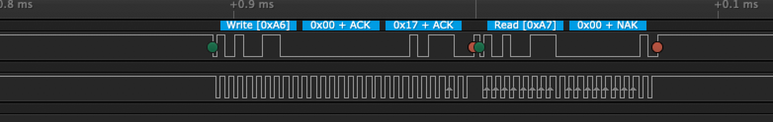
And when I run it this is what I obtain on the Logic Analyser
The expected result of the reading from register 0x0017 is 0x24 for my ST25 device, so when I get 0x40 something is wrong.
By looking at the logic trace, it seems that the second byte of the address (0x17) is never transmitted.
On the other hand, if instead of using the code
    EUSCI_B_I2C_masterSendMultiByteNext(EUSCI_B1_BASE,
         0x0017 & 0xFF
        );
I use the code
    EUSCI_B_I2C_masterSendMultiByteFinish(EUSCI_B1_BASE,
         0x0017 & 0xFF
        );


then I get the two bytes correctly transmitted, but the reading is still wrong, because the ST25 datasheet clearly states that to read from a specified register, there should be no Stop condition before
starting to read (logic trace below).
So my question is: how can I transmit the 2 address bytes correctly (like in the second screenshot), but without sending a stop condition (like in the first case)?
Is it possible to do this by using the driverlib, or am I forced to hand-write the proper values in the eUSCI registers?
Thanks in advance for the help!
