I'm using an MSP430F2410 (without DMA) with USCIB0 as an I2C master, and trying to modify the TI_USCI_I2C_master.c code (from app note slaa382a) to support a repeated-start transaction. The code needs to issue an I2C start, write the slave address and a command byte to the slave, then issue a repeated-start condition, then read some number of bytes of data back from the slave.
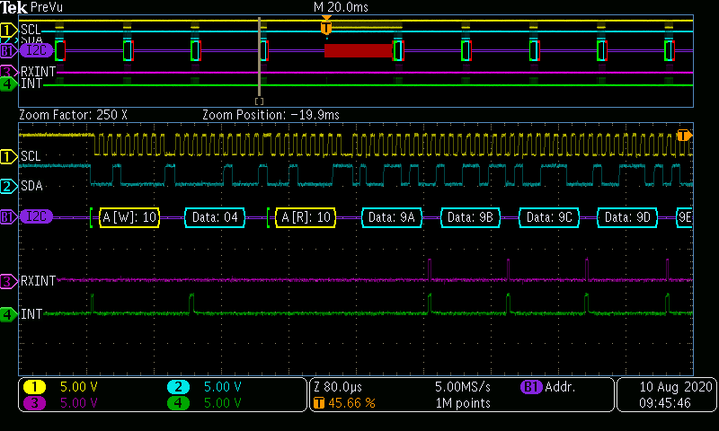
This works fine most of the time as can be seen in this scope shot (ch 4 is a test point set high when in the USCIAB0TX_ISR; ch 3 is a test point set to indicate that we're handling the RX case within the ISR):
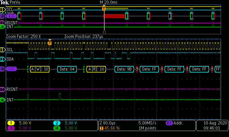
Occasionally (on the order of once every 20 to 200 read transactions), I get a situation where the repeated-start transaction appears to take place just fine, but the interrupts after the repeated-start never happen, causing the MSP430 master to not ACK the read from the slave, and then the I2C slave bails on the remainder of the transaction. Worse, the MSP430 master keeps endlessly toggling SCL until I do the next read transaction, keeping the I2C bus tied up. Here's a bad read (note lack of activity on INT and RXINT after repeated start):
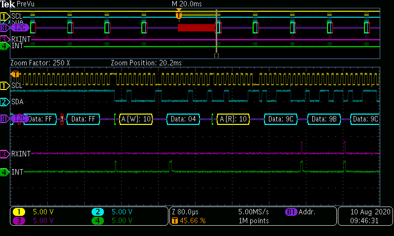
...followed by the next read, which stops the flogging of SCL and works fine:
I'm reaching my wits' end on this one, especially because it's intermittent and I've thus far not figured out a way to get the debugger to breakpoint when it happens. Anybody else ever seen anything like this? It almost seems as though the I2C state machine in the MSP430 gets "stuck" somehow on the first RX data byte after the repeat-start, never completely receiving the data byte and thus not triggering the RX interrupt and continuing to flog SCL.
I've modified the code as follows (my edits in TI_USCI_I2C_master.c flagged with "BDRTEMP"):
----------------------------------------------------------------------------------------------------------------------------
Calling code:
TI_USCI_I2C_transmitinit(SLAVE_ADDR, I2C_BAUD_PRESCALE);
while (TI_USCI_I2C_notready());
TxBuffer[0] = 0x04;                // Command byte to slave
TI_USCI_I2C_transmit_repeat_start(1, 22, (unsigned char *) TxBuffer, (unsigned char *) RxBuffer);
while (TI_USCI_I2C_notready());
----------------------------------------------------------------------------------------------------------------------------
Modified TI_USCI_I2C_master.c:
#include "TI_USCI_I2C_master.h"

signed char byteCtr;
signed char rxByteCtr;      //BDRTEMP
unsigned char *TI_receive_field;
unsigned char *TI_transmit_field;

extern struct I2Cflags_struct I2Cflags;         //BDRTEMP

//------------------------------------------------------------------------------
// void TI_USCI_I2C_receiveinit(unsigned char slave_address,
//                              unsigned char prescale)
//
// This function initializes the USCI module for master-receive operation.
//
// IN:   unsigned char slave_address   =>  Slave Address
//       unsigned char prescale        =>  SCL clock adjustment
//-----------------------------------------------------------------------------
void TI_USCI_I2C_receiveinit(unsigned char slave_address, unsigned char prescale)
{
  P3SEL |= SDA_PIN + SCL_PIN;                 // Assign I2C pins to USCI_B0
  UCB0CTL1 = UCSWRST;                        // Enable SW reset
  UCB0CTL0 = UCMST + UCMODE_3 + UCSYNC;       // I2C Master, synchronous mode
  UCB0CTL0 |= UCMM;                         //BDRTEMP Enable multi-master
  UCB0I2COA = UCGCEN | I2C_OWN_ADDR;        //BDRTEMP
  UCB0CTL1 = UCSSEL_2 + UCSWRST;              // Use SMCLK, keep SW reset
  UCB0BR0 = prescale;                         // set prescaler
  UCB0BR1 = 0;
  UCB0I2CSA = slave_address;                  // set slave address
  UCB0CTL1 &= ~UCSWRST;                       // Clear SW reset, resume operation
  UCB0I2CIE = UCNACKIE;
//  IE2 = UCB0RXIE;                            // Enable RX interrupt
  IE2 |= UCB0RXIE;                            // Enable RX interrupt    BDRTEMP
}

//------------------------------------------------------------------------------
// void TI_USCI_I2C_transmitinit(unsigned char slave_address,
//                               unsigned char prescale)
//
// This function initializes the USCI module for master-transmit operation.
//
// IN:   unsigned char slave_address   =>  Slave Address
//       unsigned char prescale        =>  SCL clock adjustment
//------------------------------------------------------------------------------
void TI_USCI_I2C_transmitinit(unsigned char slave_address, unsigned char prescale)
{
  P3SEL |= SDA_PIN + SCL_PIN;                 // Assign I2C pins to USCI_B0
  UCB0CTL1 = UCSWRST;                        // Enable SW reset
  UCB0CTL0 = UCMST + UCMODE_3 + UCSYNC;       // I2C Master, synchronous mode
  UCB0CTL0 |= UCMM;                         //BDRTEMP Enable multi-master
  UCB0I2COA = UCGCEN | I2C_OWN_ADDR;        //BDRTEMP
  UCB0CTL1 = UCSSEL_2 + UCSWRST;              // Use SMCLK, keep SW reset
  UCB0BR0 = prescale;                         // set prescaler
  UCB0BR1 = 0;
  UCB0I2CSA = slave_address;                  // Set slave address
  UCB0CTL1 &= ~UCSWRST;                       // Clear SW reset, resume operation
  UCB0I2CIE = UCNACKIE;
//  IE2 = UCB0TXIE;                            // Enable TX ready interrupt
  IE2 |= UCB0TXIE;                            // Enable TX ready interrupt      BDRTEMP
}

//------------------------------------------------------------------------------
// void TI_USCI_I2C_receive(unsigned char byteCount, unsigned char *field)
//
// This function is used to start an I2C commuincation in master-receiver mode.
//
// IN:   unsigned char byteCount  =>  number of bytes that should be read
//       unsigned char *field     =>  array variable used to store received data
//------------------------------------------------------------------------------
void TI_USCI_I2C_receive(unsigned char byteCount, unsigned char *field)
{
  TI_receive_field = field;
  if ( byteCount == 1 )
  {
    byteCtr = 0 ;
    __disable_interrupt();
    UCB0CTL1 |= UCTXSTT;                      // I2C start condition
    while (UCB0CTL1 & UCTXSTT);               // Start condition sent?
    UCB0CTL1 |= UCTXSTP;                      // I2C stop condition
    __enable_interrupt();
  }
  else if ( byteCount > 1 )
  {
    byteCtr = byteCount - 2 ;
    UCB0CTL1 |= UCTXSTT;                      // I2C start condition
  }
  else
    while (1);                                // illegal parameter
}

//------------------------------------------------------------------------------
// void TI_USCI_I2C_transmit(unsigned char byteCount, unsigned char *field)
//
// This function is used to start an I2C commuincation in master-transmit mode.
//
// IN:   unsigned char byteCount  =>  number of bytes that should be transmitted
//       unsigned char *field     =>  array variable. Its content will be sent.
//------------------------------------------------------------------------------
void TI_USCI_I2C_transmit(unsigned char byteCount, unsigned char *field)
{
  TI_transmit_field = field;
  byteCtr = byteCount;
  UCB0CTL1 |= UCTR + UCTXSTT;                 // I2C TX, start condition
}

//BDRTEMP start
//------------------------------------------------------------------------------
// void TI_USCI_I2C_transmit_repeat_start(unsigned char txByteCount, unsigned char rxByteCount, unsigned char *txField, unsigned char *rxField)
//
// This function is used to start an I2C commuincation in master-transmit mode, with repeat-start into master-receive mode.
//
// IN:   unsigned char txByteCount  =>  number of bytes that should be transmitted before the repeated-start
//       unsigned char rxByteCount  => number of bytes to receive after repeated-start
//       unsigned char *txField     =>  array variable. Its content will be sent.
//       unsigned char *rxField     =>  buffer to receive data
//------------------------------------------------------------------------------
void TI_USCI_I2C_transmit_repeat_start(unsigned char txByteCount, unsigned char rxByteCount, unsigned char *txField, unsigned char *rxField)
{
  TI_transmit_field = txField;
  TI_receive_field = rxField;
  byteCtr = txByteCount;
  rxByteCtr = rxByteCount;
  I2Cflags.repeatstart = 1;                     // Set so ISR doesn't send stop condition
  UCB0CTL1 |= UCTR + UCTXSTT;                 // I2C TX, start condition
}
//BDRTEMP end

//------------------------------------------------------------------------------
// unsigned char TI_USCI_I2C_slave_present(unsigned char slave_address)
//
// This function is used to look for a slave address on the I2C bus.
//
// IN:   unsigned char slave_address  =>  Slave Address
// OUT:  unsigned char                =>  0: address was not found,
//                                        1: address found
//------------------------------------------------------------------------------
unsigned char TI_USCI_I2C_slave_present(unsigned char slave_address)
{
  unsigned char ie2_bak, slaveadr_bak, ucb0i2cie, returnValue;
  ucb0i2cie = UCB0I2CIE;                      // restore old UCB0I2CIE
  ie2_bak = IE2;                              // store IE2 register
  slaveadr_bak = UCB0I2CSA;                   // store old slave address
  UCB0I2CIE &= ~ UCNACKIE;                    // no NACK interrupt
  UCB0I2CSA = slave_address;                  // set slave address
  IE2 &= ~(UCB0TXIE + UCB0RXIE);              // no RX or TX interrupts
  __disable_interrupt();
  UCB0CTL1 |= UCTR + UCTXSTT + UCTXSTP;       // I2C TX, start condition
  while (UCB0CTL1 & UCTXSTP);                 // wait for STOP condition

  returnValue = !(UCB0STAT & UCNACKIFG);
  __enable_interrupt();
  IE2 = ie2_bak;                              // restore IE2
  UCB0I2CSA = slaveadr_bak;                   // restore old slave address
  UCB0I2CIE = ucb0i2cie;                      // restore old UCB0CTL1
  return returnValue;                         // return whether or not
                                              // a NACK occured
}

//------------------------------------------------------------------------------
// unsigned char TI_USCI_I2C_notready()
//
// This function is used to check if there is commuincation in progress.
//
// OUT:  unsigned char  =>  0: I2C bus is idle,
//                          1: communication is in progress
//------------------------------------------------------------------------------
unsigned char TI_USCI_I2C_notready()
{
  return (UCB0STAT & UCBBUSY);
}

//------------------------------------------------------------------------------
// __interrupt void USCIAB0TX_ISR()
//
// USCIB0 TX/RX interrupt handler
//
//------------------------------------------------------------------------------
#pragma vector = USCIAB0TX_VECTOR
__interrupt void USCIAB0TX_ISR(void)
{
  P5OUT |= TP4;       //BDRTEMP
  if (IFG2 & UCB0RXIFG)
  {
    // Receive interrupt
    P5OUT |= TP6;     //BDRTEMP
    if (byteCtr == 1)
    {
        UCB0CTL1 |= UCTXSTP;                    // I2C stop condition
        *TI_receive_field = UCB0RXBUF;
        TI_receive_field++;
        byteCtr--;
    }
    else if ( byteCtr == 0 )
    {
        UCB0CTL1 |= UCTXSTP;                    // I2C stop condition
        *TI_receive_field = UCB0RXBUF;
        TI_receive_field++;
    }
    else
    {
        *TI_receive_field = UCB0RXBUF;
        TI_receive_field++;
        byteCtr--;
    }
    IFG2 &= ~UCB0RXBUF;     //BDRTEMP
    P5OUT &= ~TP6;      //BDRTEMP
  }
  else
  {
    // Transmit interrupt
    if (byteCtr == 0)
    {
        if (I2Cflags.repeatstart)                //BDRTEMP
        {
          // Handle bus turnaround for repeat-start read transaction
          I2Cflags.repeatstart = 0;               // BDRTEMP clear repeat start flag
          byteCtr = rxByteCtr - 1;                  //BDRTEMP load number of bytes to receive
          UCB0CTL1 &= ~UCTR;                        //BDRTEMP flip to receiver mode
          IFG2 &= ~UCB0RXIFG;                       //BDRTEMP
          IE2 |= UCB0RXIE;                            // Enable RX interrupt    BDRTEMP
          UCB0CTL1 |= UCTXSTT;                    // I2C repeat start condition
          while (!(IFG2 & UCB0TXIFG));                // BDRTEMP wait until xmitter is ready to accept data
        }
        else
        {
          UCB0CTL1 |= UCTXSTP;                    // I2C stop condition
        }
        IFG2 &= ~UCB0TXIFG;                     // Clear USCI_B0 TX int flag
    }
    else
    {
        UCB0TXBUF = *TI_transmit_field;
        TI_transmit_field++;
        byteCtr--;
    }
    IFG2 &= ~UCB0TXIFG;     //BDRTEMP
  }
  P5OUT &= ~TP4;        //BDRTEMP
}
----------------------------------------------------------------------------------------------------------
- Brian


