This thread has been locked.

If you have a related question, please click the "Ask a related question" button in the top right corner. The newly created question will be automatically linked to this question.

MSP430FR6007: Delta TOF FR6007 vs FR6047

Part Number: MSP430FR6007

Hello there.

As an experiment we have assembled four identical circuits, two populated with MSP430-FR6047s and two populated with MSP430-FR6007s.

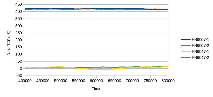
When comparing the Delta ToF between the two microcontrollers, there is a marked difference between them with the FR6047 boards being close to zero and the FR6007 boards over 400 pS.  See image below.

(This experiment was carried out by placing a flow cell in a tub of still water at room temperature. Data was collected using the latest Ultrasonic Sensing Design Center version 02_40_00_00.)

Is this to be expected from the different microcontrollers?  Besides applying a Delta ToF offset, is there anything we can do in firmware to improve this?

Thanks for your help.

F

  • Hi Foz,

    No, this isn't expected. Can you post the ADC captures for the 6007 and 6047 boards?

    BR,
    Leo

  • Thanks Leo,

    ADC captures for one of each board attached.  Let me know if you need anything else.

    Many  thanks,

    Foz Hughes

    FR6007_ADC.csvFR6047_ADC.csv

  • Hi Foz,

    The only difference I see in the signals is that the FR6007 signal is around 1000 ADC counts while the FR6047 signal is around 700 ADC counts. Can you reduce the gain of the FR6007 to give a signal with 700 ADC counts?  Can you confirm that the same version of software is used on both platforms?  

    BR,
    Leo

  • Hi Leo,

    I've  attached some more ADC captures from the two boards. 

    To be absolutely certain the boards are running the same software, I downloaded a fresh copy of UltrasonicWaterFR604x_02_40_00_00 from here, imported the projects into CCS 10.1.0.00010 and flashed them to the boards.  The only modification to the software is in USS_userConfig.h where it is sets the  USS frequency configuration to use a crystal rather than the standard ceramic resonator.

    The data was captured using the Ultrasonic Sensing Design Center version 02_40_00_00.  I have also attached the saved configuration file so you can see any settings that have been changed from standard.  The most notable difference is in USS XTAL Settling Count which is set to 3000 us to give the aforementioned crystal plenty of time to settle.

    Apart from the microcontrollers, everything else on the two boards is identical, and the captured data was taken using the same flow cell.

    Thanks for your help.

    Foz Hughes6007_ADC.csv6047_ADC.csv

    2860.USSConfig.xml
    <?xml version="1.0" encoding="UTF-8"?>
    <ussMspGui>
    	<settings>
    		<isLogging>true</isLogging>
    		<logLocation>/home/foz/USS_02_40_00_00/USSWorkspace/USS_Project</logLocation>
    	</settings>
    	<configParams>
    		<target>water</target>
    		<board>Custom-PCB</board>
    		<device>MSP430FR6007</device>
    		<lph_gpm>lph</lph_gpm>
    		<f1f2>1000.0 1020.0</f1f2>
    		<patternSeq>0</patternSeq>
    		<gapBetweenPulseAndCapture>100.0</gapBetweenPulseAndCapture>
    		<numberOfPulses>25.0</numberOfPulses>
    		<gapBetweenUpsAndDns>3000.0</gapBetweenUpsAndDns>
    		<gapBetweenDnsAndUps>300.0</gapBetweenDnsAndUps>
    		<gainControl>1.0</gainControl>
    		<areaConstant>12742000.00</areaConstant>
    		<xt2Freq>8000</xt2Freq>
    		<sigSamplingFreq>4000.0</sigSamplingFreq>
    		<adcSamplePulse>20</adcSamplePulse>
    		<deltaTOFOffset>0.0</deltaTOFOffset>
    		<absTOFAdditionDelay>0.0</absTOFAdditionDelay>
    		<captureDuration>40.0</captureDuration>
    		<intrplCorrTableSize>2</intrplCorrTableSize>
    	</configParams>
    	<devModeParams>
    		<param1>0</param1>
    		<param2>3.0</param2>
    		<param3>10000.0</param3>
    		<param4>5000.0</param4>
    		<param5>0.0</param5>
    		<param6>0.0</param6>
    		<param7>3000.0</param7>
    		<param8>11.0</param8>
    		<param9>3.0</param9>
    		<param10>0.0</param10>
    	</devModeParams>
    	<configCalibParams>
    		<maximumVFR>10000.00</maximumVFR>
    		<calculateTemp>0</calculateTemp>
    		<minTempLUT>5</minTempLUT>
    		<maxTempLUT>60</maxTempLUT>
    		<tempResLUT>1.000</tempResLUT>
    		<transducerLen>9.432</transducerLen>
    		<calibType>1</calibType>
    	</configCalibParams>
    </ussMspGui>
    

  • Hi Foz,

    Can you also test the FR6007 board with a resonator to eliminate this as a potential issue?

    BR,
    Leo

  • Hi Leo,

    I've swapped the crystal for the standard ceramic resonator on both boards and captured DToF and ADC.  The change made no discernible difference.

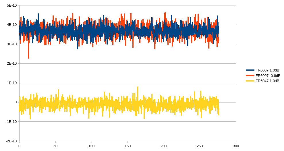
    I ran the test with the FR6007 twice because the ADC capture was a little high with a gain of 1.0dB.  This was reduced to -0.8dB for the second test.  I've attached the ADC for each capture here, with the file named FR6007-CR-ADC-RG.csv being from the FR6007 with the reduced gain setting.

    Many thanks for your help,

    Foz HughesFR6007-CR-ADC.csvFR6007-CR-ADC-RG.csvFR6047-CR-ADC.csv

  • Hi Foz,

    Another potential difference between the platforms may be in the trim register settings.  You can find documentation on these in Section 21.3.2 of the User’s Guide https://www.ti.com/lit/pdf/slau367. See Table 21-1 Trim Registers.   Can you check the trim register settings for your 6047 board and compare these settings to the ones on your 6007 board?

    BR,
    Leo

  • Hi Leo,

    I don't think we're able to access the trim values that are stored to the device boot data memory.  If there is a way to do that, please let me know and I'll find out.

    In the firmware (which is vanilla) the values are set as follows:

    FR6007:

        SAPHCH0PUT = 0x00;    SAPHCH0PDT = 0x0F;    SAPHCH0TT  = 0x0F;
        SAPHCH1PUT = 0x0F;    SAPHCH1PDT = 0x00;    SAPHCH1TT  = 0x00;

    FR6047:

        SAPHCH0PUT = 0x0F;    SAPHCH0PDT = 0x0E;    SAPHCH0TT  = 0x0E;
        SAPHCH1PUT = 0x0F;    SAPHCH1PDT = 0x0E;    SAPHCH1TT  = 0x0E;

    So they are different.  However, as I understand it those values are only used if TEST_TRIM_CONST is defined in hal_system.h, which is commented out on both the FR6007 and FR6047 vanilla firmware.  Hence, the MCUs should be using trim values that were programmed into them during manufacture.

    It it worth tweaking the trim values in the firmware?  How will any changes relate to the values of the capacitor & resistor in their respective input and output channels?

    Many thanks,

    Foz Hughes

  • Hi Foz,

    I think the simplest solution would be to simply adjust the dToF offset to compensate for this difference on the FR6007.

    BR,
    Leo

  • Hi Leo,

    Thanks for your response.  While I appreciate all your help, providing a workaround doesn't help to resolve this issue.  The datasheet for the FR6007 claims it is capable of "<100ps differential time-of-flight (dTOF) accuracy" but the testing we have carried out doesn't appear to agree with that.  As it is, we don't feel that the accuracy of the FR6007 can be trusted, particularly for use in a commercial product.  Is there a way to escalate this issue?

    Many thanks for all your help.

    Foz Hughes

  • Hi Foz,

    The <100ps dToF accuracy is referring to the accuracy after calibration.  Although the offset you are seeing is unusually high, it would still be considered a dToF offset problem(not an accuracy problem). I've sent you a friend request for further discussion.

    BR,
    Leo

**Attention** This is a public forum