This thread has been locked.

If you have a related question, please click the "Ask a related question" button in the top right corner. The newly created question will be automatically linked to this question.

MSP430FR2676: Increase CapTIvate sample rate

Part Number: MSP430FR2676


Hello,

Currently I am working on a project using the MSP430FR2676 microcontroller with the CapTIvate peripheral. I started designing by using the TI Captivate Design Center, generate the source code, and by starting tuning the variables. One of the variables that is adjustable and has a great impact on the sample rate is the Active Mode Scan Rate and I managed to get the sample rate to 1ms (1KHz).

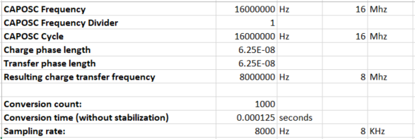
However, this sample rate is not sufficient for our solution in the product and therefore we would like to increase the sample rate to approximately 8-10kHz. After investigating the Technology Guide and using formulas at the page: Optimizing for the shortest measurement time. it seems to be feasible.

After investigating the generated code, increasing the MCLK to 16MHz, registering a new callback, we found out that a lower level call to the ROM code “CAPT_updateSensor” and “CAPT_updateSensorRawCount” takes approximately 0.5-0.6ms. The self created callback that was registered is fast as expected (1us). By using the “CAPT_updateSensor” method as time reference it can be determined that (1/0.0005)=2000Hz=2kHz can be the maximum sample rate of this solution.

Based on the information above I am not sure on how to improve the sample rate. On the TI Captivate Technology Guide there is a lot of information on how to optimize this peripheral for power consumption. Is there more information on how to optimize the sample rate of this peripheral? Or are there any TI examples available with higher sample rates? Or does anybody have experiences with this?

  • Hi Randy,

    The time it takes to sample/convert is primarily determined by the number of sensors, their target conversion count and the conversion clock frequency.

    Of course there is the additional overhead of processing each sample to determine if there is a prox or touch event and then your callback to respond accordingly.

    Let's break it down and see if we can find you some speed improvement, and I want to set the expectation that won't be able to go much faster than the 1KHz you currently can achieve.  Certainly not 8-10KHz.  Captivate technology is designed for HMI applications where 10-20ms sample rates are more than sufficient to meet the speed of finger presses on a sensor.

    Here is how it works:

    Let's assume you have only one sensor and it has a target conversion count = 250 and you are using an F/4 (as shown in the GUI) which is 4MHz.

    Since the conversion requires 2-clock cycles, one for the charge phase and one for the transfer phase, so the effective conversion rate is 2MHz or 0.5usec period.  This means the sensor requires 250 x 0.5usec = 125usec to perform a conversion.  Assuming this is a self capacitive sensor, then additional capacitance (typically from a touch or whatever it is you are trying to detect) will lower the conversion count by say 10% so the time is a little shorter.

    There is a feature of the Captivate where its 1.5v LDO is placed in a lower power state in between conversions(by default).  However, at the start of each new conversion sequence the LDO needs to come up to stabilization before the conversion can begin, adding about 125-150us to each measurement.  This can be disabled, keeping the LDO on all the time (consumes a little more power, but if not operating on battery it is a don't care).  This is done by setting the .bLpmControl = true in your CAPT_UserConfig.c sensor struct. So your total conversion time is now 125us (LDO delay) + 125us (conversion time) = 250usec or 4KHz.  Try disabling this feature and your maximum sample/conversion rate should now be ~8KHz.

    But don't forget the overhead the software has to perform around each measurement and to your point, yes it can add a few 100's of usec, if using the default code generated by the GUI.  You can skip all the extra processing and simply grab the raw conversions and process on your own. That will save a bunch of time.  Not sure how much - you will have to set it up and try.

    You would use the CAPT_updateSensorRawCount() function.  Note, it doesn't do any sensor processing or call your callback.  There is an example of this in the Captivate Technology Guide, software chapter.

    Hereis the simplest and fastest Example that I know:

    (assums only one sensor, one cycle)

    main.c{

    // configure your IO and clock system

    configure IO;
    configure clocks;

    // configure captivate peripheral (you will need to look at each function to pass appropriate arguments)

    MAP_CAPT_powerOn();
    MAP_CAPT_reset();
    CAPT_init();
    MAP_CAPT_initSensorIO();
    MAP_CAPT_enableSensorIO();
    CAPT_initSensor();

    // call initial calibration
    CAPT_calibrateSensor();

    // Setup Captivate timer to generate a wake up interrupt to match your desired scan rate
    MAP_CAPT_stopTimer();
    MAP_CAPT_clearTimer();
    MAP_CAPT_selectTimerSource(CAPT_TIMER_SRC_ACLK);
    MAP_CAPT_selectTimerSourceDivider(CAPT_TIMER_CLKDIV__1);
    MAP_CAPT_writeTimerCompRegister(CAPT_MS_TO_CYCLES(1)); // used 1 for 1msec
    MAP_CAPT_startTimer();
    MAP_CAPT_enableISR(CAPT_TIMER_INTERRUPT);

    LOOP{

    CAPT_updateSensorRawCount();

    Process raw data(); // this would do what you do in your callback

    LPM3;

    }

    }// end main

    Does this help?

  • Hello Dennis,

    Thank you for your very detailed answer! It is correct that I use a single sensor and one cycle. The example that you provided is exactly what I also tried to do, strip all code that is not necessary and use the CAPT_updateSensor() method, and another try with the CAPT_updateSensorRawCount() method.

    By using the CAPT_updateSensor() method the execution time is 0.68 ms, by using the CAPT_updateSensorRawCount() the execution time is 0.55 ms. I tried your suggestion to set bLpmControl to true and use the CAPT_updateSensorRawCount() method and measured that the execution time is around 0.48 ms.

    Another solution where I was thinking of, the peripheral uses the ACLK source which is 32KHz, when writing to the MAP_CAPT_writeTimerCompRegister(CAPT_MS_TO_CYCLES(1)), the CAPT_MS_TO_CYCLES macro converts the 1 ms to 32 cycles.

    Is there a possibility to optimize this? Or is it possible to not use this CapTIvate timer but instead of using the timer use a polling method to get the desired scan rate?

  • Hi Randy,

    The captivate timer is actually sourced from the ACLK by default in the startup software, operating at 32KHz.

        MAP_CAPT_selectTimerSource(CAPT_TIMER_SRC_ACLK);

    The macro CAPT_MS_TO_CYCLES  = #define CAPT_MS_TO_CYCLES(ms)     (ms * 32) so it is only a multiplier of the 32KHz clock period.

        MAP_CAPT_selectTimerSourceDivider(CAPT_TIMER_CLKDIV__1);

    A value of '1' for the .ui16ActiveModeScanPeriod results in a compare register value of '32' -> 32 / 32768  = ~ 1msec.

        MAP_CAPT_writeTimerCompRegister(CAPT_MS_TO_CYCLES(g_uiApp.ui16ActiveModeScanPeriod));

    You could bypass the macro CAPT_MS_TO_CYCLES(ms) and pass a value directly.  For example, if you used a value of 10, that would translate to 10  / 32768 = ~305usec.

    Here is Captivate timer illustration for reference. I'm sure you have read through the Captivate Technology Guide, Technology chapter, but for those reading this, here is a link that describes more.

    In regards to using any of the MSP430 general purposes timers, yes, you could set one up and poll.  This works perfectly fine, but you could do the same with the Captivate timer using its CAPTIFG flag, which is exactly what the default code uses in the CAPT_ISR.  This is more power efficient, which is important for battery powered applications since the MCU can enter its low power state in between the interrupts.  Since speed is the goal its probably faster to setup a timer and just poll it's IFG bit (with IE bit disabled) in a tight software loop.

    It is possible to set the timer up to automatically kick off the conversion and you can use the EOCIFG flag as a notification.

    I have attached an example main.c showing how to do this.  The timer will automatically trigger the next conversion while the CPU remains in LPM0 until an CAPT_END_OF_CONVERSION_INTERRUPT is generated.  The time to read the raw results takes about 2.5usec.  You could probably make it go a little faster by not enabling the EOC interrupt and have the CPU sit and poll on the EOC flag.  Not sure this will help though because the biggest delay is the conversion time itself (100s of usec).  Give it a try.

    /* --COPYRIGHT--,BSD
     * Copyright (c) 2017, Texas Instruments Incorporated
     * All rights reserved.
     *
     * Redistribution and use in source and binary forms, with or without
     * modification, are permitted provided that the following conditions
     * are met:
     *
     * *  Redistributions of source code must retain the above copyright
     *    notice, this list of conditions and the following disclaimer.
     *
     * *  Redistributions in binary form must reproduce the above copyright
     *    notice, this list of conditions and the following disclaimer in the
     *    documentation and/or other materials provided with the distribution.
     *
     * *  Neither the name of Texas Instruments Incorporated nor the names of
     *    its contributors may be used to endorse or promote products derived
     *    from this software without specific prior written permission.
     *
     * THIS SOFTWARE IS PROVIDED BY THE COPYRIGHT HOLDERS AND CONTRIBUTORS "AS IS"
     * AND ANY EXPRESS OR IMPLIED WARRANTIES, INCLUDING, BUT NOT LIMITED TO,
     * THE IMPLIED WARRANTIES OF MERCHANTABILITY AND FITNESS FOR A PARTICULAR
     * PURPOSE ARE DISCLAIMED. IN NO EVENT SHALL THE COPYRIGHT OWNER OR
     * CONTRIBUTORS BE LIABLE FOR ANY DIRECT, INDIRECT, INCIDENTAL, SPECIAL,
     * EXEMPLARY, OR CONSEQUENTIAL DAMAGES (INCLUDING, BUT NOT LIMITED TO,
     * PROCUREMENT OF SUBSTITUTE GOODS OR SERVICES; LOSS OF USE, DATA, OR PROFITS;
     * OR BUSINESS INTERRUPTION) HOWEVER CAUSED AND ON ANY THEORY OF LIABILITY,
     * WHETHER IN CONTRACT, STRICT LIABILITY, OR TORT (INCLUDING NEGLIGENCE OR
     * OTHERWISE) ARISING IN ANY WAY OUT OF THE USE OF THIS SOFTWARE,
     * EVEN IF ADVISED OF THE POSSIBILITY OF SUCH DAMAGE.
     * --/COPYRIGHT--*/
    //#############################################################################
    //
    //! \file   main.c
    //!
    //! \brief  This demo utilizes the first four buttons of the CAPTIVATE-BSWP
    //!         sensing panel to demonstrate how an application with just 4
    //!         buttons can be measured autonomously using the wake-on-proximity
    //!         state machine, requiring no CPU interaction when no touch is
    //!         occuring.  This provides a low power consumption of 3uA-avg,
    //!         or 750nA per button.
    //
    //  Group:          MSP
    //  Target Devices: MSP430FR2676
    //
    //  (C) Copyright 2015, Texas Instruments, Inc.
    //#############################################################################
    // TI Release: 1.80.00.30
    // Release Date: March 26, 2019
    //#############################################################################
    
    //*****************************************************************************
    // Includes
    //*****************************************************************************
    
    #include <msp430.h>                      // Generic MSP430 Device Include
    #include "driverlib.h"                   // MSPWare Driver Library
    #include "captivate.h"                   // CapTIvate Touch Software Library
    #include "CAPT_App.h"                    // CapTIvate Application Code
    #include "CAPT_BSP.h"                    // CapTIvate EVM Board Support Package
    
    //*****************************************************************************
    // Function Implementations
    //*****************************************************************************
    #define CAPREG16(base,offset)                                                            \
            (*((volatile uint16_t*)((uint16_t*)base+(uint8_t)offset)))
    
    /* Hidden Peripheral Register: CAPCVD0, @ 0x00A90 */
    #define CAPCVD0_ADDRESS (0x00A90)
    #define CAPCVD0 (*(volatile uint16_t*)CAPCVD0_ADDRESS)
    
    void startTimerConversionMode(tSensor* pSensor, uint8_t ui8Cycle, uint16_t ui16ScanPeriod);
    void CAPT_stopTimerConversionMode(tSensor* pSensor, uint8_t ui8Cycle);
    
    // This example is written for MSP430FR2676
    void main(void)
    {
        volatile uint16_t ui16Result;
    	//
    	// Initialize the MCU
    	// BSP_configureMCU() sets up the device IO and clocking
    	// The global interrupt enable is set to allow peripherals
    	// to wake the MCU.
    	//
    	WDTCTL = WDTPW | WDTHOLD;
    	BSP_configureMCU();
    	__bis_SR_register(GIE);
    
    	//
    	// Start the CapTIvate application
    	//
    	//CAPT_appStart();
    	 MAP_CAPT_powerOn();
    	 CAPT_init();
    
        CAPT_selectInputImpedanceBiasCurrent(CAPT_INPUT_IMPEDANCE_BIAS_CURRENT);
        CAPT_selectElectrodeChargeVoltageSource(eVRegSupply);
    
        MAP_CAPT_initSensorIO(&Sensor);
        MAP_CAPT_enableSensorIO(&Sensor);
        CAPT_initSensor(&Sensor);
    
        CAPT_calibrateSensor(&Sensor);
    
        startTimerConversionMode(&Sensor, 0, 1);
    
    	//
    	// Background Loop
    	//
    	while(1)
    	{
    		CAPT_appSleep();
    
    
    		if(g_bEndOfConversionFlag == true)
    		{
    		    // @16MHz, CPU can execute this section of code 2.5usec (measured)
    
    		    // Set IO pin for logic probe
    	        P1OUT |= BIT6;
    		    g_bEndOfConversionFlag = false;
    
    		    // Read 'raw' result directly from IP
    		    ui16Result = CAPREG16(&CAPCVD0,Sensor.pCycle[0]->pElements[0]->ui8RxBlock);
    
    		    // breakpoint to examine results
    		    _no_operation();
    
                P1OUT &= ~BIT6;
    
    
    		}
    
    	} // End background loop
    } // End main()
    
    
    void startTimerConversionMode(tSensor* pSensor, uint8_t ui8Cycle, uint16_t ui16ScanPeriod)
    {
        MAP_CAPT_applySensorParams(pSensor);
        MAP_CAPT_applySensorFreq(CAPT_OSC_FREQ_DEFAULT, pSensor);
        MAP_CAPT_loadCycle(pSensor, ui8Cycle, CAPT_OSC_FREQ_DEFAULT, true);
    
        // Apply bias current trim for all frequency offsets if necessary
    #if defined(CAPT_HAS_INPUT_IMPEDANCE_BIAS_CURRENT) && (CAPT_HAS_INPUT_IMPEDANCE_BIAS_CURRENT==true)
        uint8_t ui8Element;
        for (ui8Element = 0; ui8Element < pSensor->pCycle[ui8Cycle]->ui8NrOfElements; ui8Element++) {
            MAP_CAPT_selectInputImpedanceBiasCurrentTrim(pSensor->pCycle[ui8Cycle]->pElements[ui8Element]->ui8InputBiasExtractTrim,
                    pSensor->pCycle[ui8Cycle]->pElements[ui8Element]);
        }
    #endif  // CAPT_HAS_INPUT_IMPEDANCE_BIAS_CURRENT
    
        MAP_CAPT_stopCCounter();
        MAP_CAPT_clearIFG(
                CAPT_DETECTION_INTERRUPT |\
                CAPT_MAX_COUNT_ERROR_INTERRUPT |\
                CAPT_CONVERSION_COUNTER_INTERRUPT |\
                CAPT_END_OF_CONVERSION_INTERRUPT |\
                CAPT_TIMER_INTERRUPT
                );
    #if 1
           MAP_CAPT_stopTimer();
           MAP_CAPT_clearTimer();
           MAP_CAPT_selectTimerSource(CAPT_TIMER_SRC_ACLK);
           MAP_CAPT_selectTimerSourceDivider(CAPT_TIMER_CLKDIV__1);
           MAP_CAPT_writeTimerCompRegister(CAPT_MS_TO_CYCLES(ui16ScanPeriod));
           MAP_CAPT_startTimer();
           MAP_CAPT_enableISR(CAPT_END_OF_CONVERSION_INTERRUPT);
    #endif
        g_bConvCounterFlag = false;
        g_bMaxCountErrorFlag = false;
        g_bDetectionFlag = false;
        MAP_CAPT_enableTimerTrigMeasurement();
        MAP_CAPT_setCAPSTART();
    }
    
    void CAPT_stopTimerConversionMode(tSensor* pSensor, uint8_t ui8Cycle)
    {
        IQ16_t LTA;
        uint8_t ui8Element;
    
        MAP_CAPT_disableTimerTrigMeasurement();
        MAP_CAPT_stopCCounter();
        MAP_CAPT_disableISR(
                CAPT_DETECTION_INTERRUPT |\
                CAPT_MAX_COUNT_ERROR_INTERRUPT |\
                CAPT_CONVERSION_COUNTER_INTERRUPT
            );
        MAP_CAPT_unloadCycle(pSensor, ui8Cycle, 0, true);
        // Need to update struct LTA from the FSM in all cases after exiting WakeOnProx Mode to fix the
        // LTA drifting not handled by CAPT_saveCycleResults inside CAPT_unloadCycle.
        for(ui8Element = 0; ui8Element < pSensor->pCycle[ui8Cycle]->ui8NrOfElements; ui8Element++)
        {
            LTA = MAP_CAPT_readLTA(pSensor->pCycle[ui8Cycle]->pElements[ui8Element]->ui8RxBlock);
            pSensor->pCycle[ui8Cycle]->pElements[ui8Element]->LTA.ui16Natural = LTA.ui16Natural;
            pSensor->pCycle[ui8Cycle]->pElements[ui8Element]->LTA.ui16Decimal = LTA.ui16Decimal;
        }
    }
    

  • Hello Dennis,

    Thank you for your answer! I tried the suggestion that you made and this solution seems to work. I have seen that with a low count value the execution time can be reduced to 1usec when polling and to 2-2.5usec when using the low power mode mode. I will continue more testing tomorrow.

    The code seems to work now since direct registers are accessed, I could not find out the function implementation of the CAPREG16() method and of the "hidden peripheral registers" in the datasheet of the microcontroller or in the technology guide. Is this something which is available for everyone?

  • Hello Dennis,

    I continued my testing of yesterday this morning and there are a few things that I can not relate. I managed to get a sample rate of 10,93KHz by setting the count register to 250, the gain to 100 and the MAP_CAPT_writeTimerCompRegister (in following texts referred as Compare Register Value) method has the value 2 as input.

    When I start to increase the count value, in this example I used 1000, then I also need to increase the CompRegister value to 20. But since I incremented the CompRegister value the sample rate drops to around 1600Hz as I calculated in the table below.

    Captivate Timer frequency ACLK = 32768Hz
    Period 1 / TimerFrequency = 0.000030517578125
    Compare register value 20
    Maximum sample frequency 1 / (CompareRegisterValue * Period) = 1638 Hz

    When I decrease the compare register value, the CAPREG16() function does not output a stable value. If the compare register is close to the correct value it will incidently output a 0, when the value is not even close to the correct compare register value it will only output 0's. This same behavior happens when the poll frequency is to high.

    When I calculate the conversion/sample rate based on the CAPOSC frequency and frequency divider I have a theoretical sample rate of 8KHz, see calculation below.

    By investigating this test output, there are a few things which are not clear to me:

    • How is it possible that the CAPREG16() method outputs 0's when the compare register value is not high enough? It seems to have enough time to do the conversion.
    • How does the gain relate to the conversion/sample time? Is it correct that when you increase the gain that the time to fill the count takes less time and thus increases your sample rate?

  • Hi Randy,

    Here the is complete calculation.  What's not documented is a 20us stabilization required by the AFE at the beginning of each conversion.  Also, disabling the LDO warmup  (.bLpmControl = true) saves additional 125us, so in your 1000 conversion count case you are actually topped out at 6.8KHz.

    You are correct - If you set the Timer's compare value to 20, you calculate 1638Hz (610usec period).

    So you are attempting to read the timer register, not the compare register - correct?

    A word of caution, although if you are using ACLK or REFO clock for the Captivate timer source this shouldn't be an issue:

    Yes, regarding the gain and conversion/sample time, with mutual capacitance as you change the dielectric between the electrodes (dielectric value goes up compared to air), so does the capacitance between the electrodes.  As the capacitance increases, so does the amount of charge each time it is charged and consequently the number of charge/transfers gets smaller since you are filling up the internal sample capacitor more with each transfer until the threshold is hit.

    Here is example:

  • Hello Dennis,

    Thank you for the information. The LDO was already disabled, e.g. .bLpmControl was set to true but it is good to know that this has impact on the time. I now understand that the maximum frequency should be around 6.8 KHz when the count is set to 1000 because of the stabilization time that I didn't add in my calculations.

    I'm not really sure what you mean with the question: "So you are attempting to read the timer register, not the compare register - correct?". I am not attempting to read any timer register or compare register but trying to read the raw count from the register using the method CAPREG16(&CAPCVD0, ...). However, I use the captivate timer and the compare register to retrieve the value. As I understand the maximum frequency for the count value is 1000 is 6.8 KHz, so if I use a compare register value of 5 (32768 / 5 = 6553.6 Hz then I should be able to retrieve the raw count. See image for the code section where I set the compare register to 5 and the ACLK is selected. 

    When running the code with compare value 5, I still do not retrieve any value from the register, see debug session image:

    I was expecting that this would work since it now matches all the calculations that were made, however the register still returns the the zeroes. I hope that you have some more suggestions for me, because I think that we are almost there.

    Thanks in advance!

  • Hello Dennis,

    Here is an update from our side. With your help we managed to get the system working with a conversion count of 1000 at a sample rate of 3.5 KHz. But when we increase the sample rate, we see that the register starts outputting zeroes. However, when we increase the capacitance by putting our finger between the electrodes or decrease the space between the electrodes we see that the register starts outputting a value with the sample rate of 6.5 KHz. In this case we receive values around 400-450, but are not able to achieve the count of 1000.
    The first idea at our side was to trigger a calibration with this decreased space. We calibrate the sensor by restarting the microcontroller/code, which calls the CAPT_calibrateSensor() method when starting. But again we observe that the register outputs zero values. When we again decrease the space between the electrodes it starts outputting values, but again not close to the conversion count 1000.

    Is there are limitation towards the other end of the spectrum? We now know that the system gives a max count error at 8191 counts to prevent the system from running forever. However, it seems now that if the sample rate is increased that the system returns a 0 if count becomes higher than a certain value. We get the idea that the system takes longer to obtain the wanted counts than is possible due to the sample rate frequency and a 0 is returned as protection. Do you know if there is a kind of protection/condition build in?

    We do not completely understand why this is happening and would like to know how this can happen. Could you provide us an answer to this?

    Thank you!

  • Hi Randy,

    Since you are operating the Captivate at an extreme end of its performance it is hard to say exactly what is happening here.  I am in the process of setting up an experiment to duplicate what you are attempting.  This will give me a first hand look and what you are seeing.

**Attention** This is a public forum