This thread has been locked.

If you have a related question, please click the "Ask a related question" button in the top right corner. The newly created question will be automatically linked to this question.

CCS/MSP430F5528: Initiate P5.2 and P5.3 as GPIOs

Part Number: MSP430F5528


Tool/software: Code Composer Studio

I am new to the MSP430 software, I am using the MSP430F5528 with the MSP-TS430RGC64USB breakout board for testing.

I am trying to configure Port P5 for output, to do a basic LED blink function. I want to use both P5.2 and P5.3, and have the LED’s blink separately, controlled by two separate functions.

I am having problems initiating the Port P5.

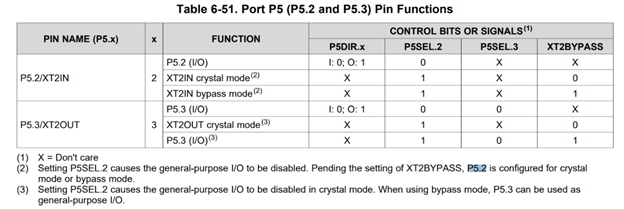
I read the Data Sheet for my particular chip, but with my limited knowledge the information was not particular helpful to me. Here is the Data Sheet Information:

After reading thought several Forums and MSP430 GPIO tutorials, I produced the following code to initiate the pins/ports.

       P5SEL |= BIT0;      //SEL set GPIO BIT0 sets as output

       P5DIR |= BIT2 | BIT3;       //DIR set Direction BIT2 & BIT3 sets as output

       P5OUT |= BIT2 | BIT3;            //Sets P5.2 & P5.3 as High

But it was not successful to send power to the LEDs.

I used a similar code to initiate Port P4 and had success. I know the Port Functions are different between the P4 and P5 ports.

I hope you can help me with this problem and inform me what I am doing wrong.

  • Hi Nicole,

    The image you attached did not come through.

    I think you need to set P5SEL.2 to 0 to configure P5.2 & P5.3 as outputs.

    You will need P5SEL &= ~BIT2;      //SEL set GPIO P5.2 & P5.3 sets as input/output

    Also, looking at the schematics for MSP-TS430RGC64USB at page 116, section B.28 MSP-TS430RGC64USB, of the HW Tool User's Guide at https://www.ti.com/lit/pdf/slau278,

    P5.2 & P5.3 are routed to XT2IN & XT2OUT.

    Where are they connected to LEDs?

    Srinivas

  • I've tried to upload the Table again. It is Table 6-51, page 92, of the https://www.ti.com/lit/ds/symlink/msp430f5528.pdf?ts=1598027071355

    You're suggestion of  P5SEL &= ~BIT2; makes sense based on the Table 6-51. As I was confused of the Control P5SEL.2 meant. But sadly this line did not make a difference in my code. 

    The LEDs are connected directly to the pins on the board. I did notice when looking at the schematic for the MSP-TS430RGC64USB that these pins are connected to XT2IN and XT2OUT which connects the BSL.  In the schematic on page 113, it show a 0 ohm resistor connecting the XT2IN/OUT lines back to the pins. Does this mean I need to add a 0 ohm resistor to access these pins or do you think I need to hard code the XT2IN/OUT to be turned off by disabling XT2 completely (I've tried, UCSCTL6 |= XT2OFF, but the results were negative). 

**Attention** This is a public forum