This thread has been locked.

If you have a related question, please click the "Ask a related question" button in the top right corner. The newly created question will be automatically linked to this question.

CCS/MSP430FR2433: Is it possible to make a GPIO float?

Part Number: MSP430FR2433

Tool/software: Code Composer Studio

Hello 

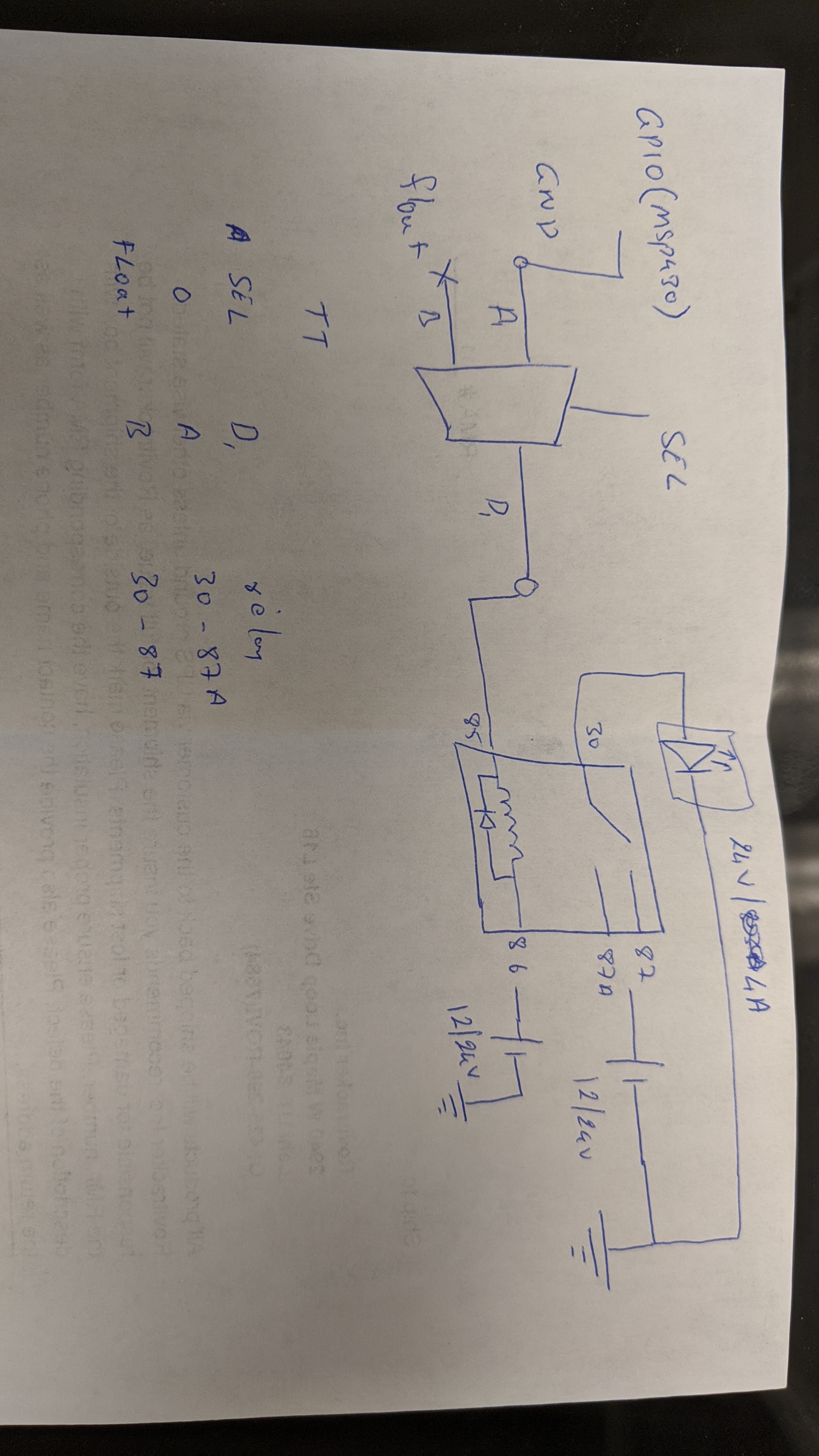
I'm working on msp430fr2433 and was wondering if it's possible to float a GPIO. I need this GPIO to control a relay. I'll connect one side of the coil of the relay to 12V while the other will be connected to GPIO. 

When GPIO is GND, the coil conducts and the relay turns ON. 

When GPIO floats, the coil doesn't conduct and the relay turns OFF. 

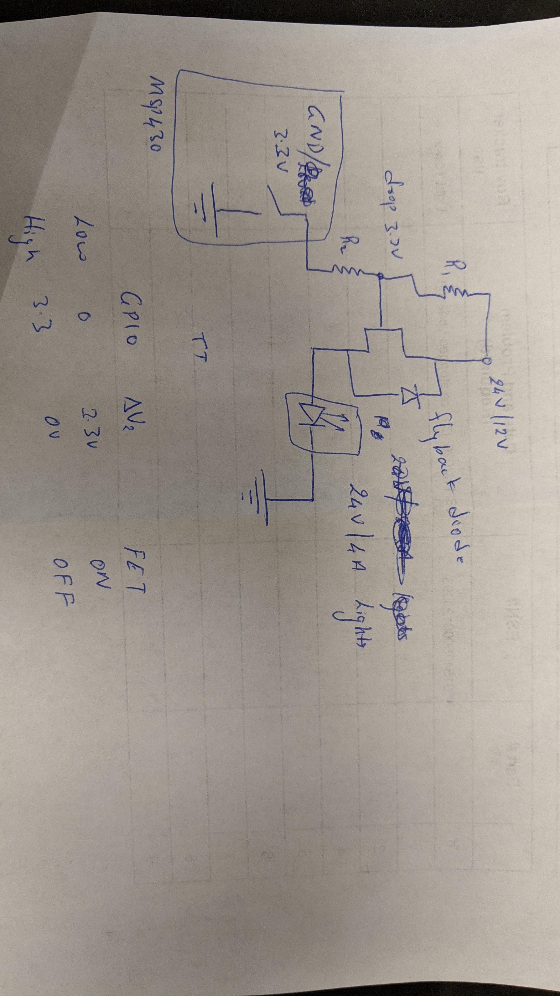
Is it possible? or you guys recommend using a FET or something. 

Varun R

  • You can make a GPIO output float by configuring it as an input. But you cannot drive the relay that way because the GPIO pins have diodes that clamp the voltage to the power rails. Which means that your relay will still be powered on. But with one side connected to 3.3V rather than ground.

    A transistor driver of some sort is required and a diode across the relay coil should be used to protect the driver.

  • How about I use a MUX. 

    SEL line will be connected to GPIO configured as an input. 

    A of the MUX will be connected to GND

    B of the MUX will be connected to nothing. Float. 

    GPIO input 0 = GND at the output of the MUX 

    GPIO input 1 = Float at the output of the MUX 

    Will this work? Certainly easier than a transistor driver right. 

    Varun R

  • Does the MUX have clamping diodes?

    Pretty much nothing is simpler than a transistor relay driver.

  • I'm still thinking of a circuit that would serve the purpose. Does it need clamping diodes? one input of Mux is connected to GND while the other is not connected. The output of the MUX is connected to a relay coil which has an inbuilt flyback diode. The relay is connected to a 24V battery to LED lighting which consumes 4A at 24V. I am using NC configuration for the relay. 

    I have attached the circuit diagrams of how I plan on implementing this. one is via MUX while the other is with a FET.  Please let me know which one is the best. You can say neither as well. I'll work on it more.

  • Be aware that I had edited my last post to remove some errors.

  • Not enough. Placing the NPN transistor on the high side of the relay coil limits the coil voltage to about 0.7V less than the GPIO output voltage.

    A resistor to limit base current is almost always a good idea.

  • Hello 

    Thank you for your suggestion. I really appreciate it. 

    Varun R

  • Varun:

    As an alternative, you could use a silicon controlled rectifier (SCR).

    The 100 Ohm resister lowers the output voltage to 1.5 VDC and current to 15 mA. Let's assume the SCR is a SJxx06xx Series by Littlefuse. That SCR can handle 6A at 600V going through it, and it only needs .2 to 15 mA to trigger it. It costs about $2.

  • The SCR is great if you never want to turn it off after it is triggered.

  • Well...that is both embarrassing and humbling. I should of went with my initial solution: a phototransistor in an optocoupler.

  • The current transfer ratio of an optocoupler is typically too low to let it drive a relay but they can easily drive a transistor. Kind of complicated so you need to have a very good reason to avoid the simplicity of low side drivers.

    For multiple relays the ULN2803 is very handy.

  • I think I'll buy a couple of those ULN2803 devices. Thanks!

  • Hello Varun,

    It's been a few days since we have heard from you so I will assume you found a working solution so I will mark this as resolved.

    If this isn’t the case, please click the "This did NOT resolve my issue" button and reply to this thread with more information.
    If this thread locks, please click the "Ask a related question" button and in the new thread describe the current status of your issue and any additional details you may have to assist us in helping to solve your issues.

    BTW, thanks to all who contributed on this one!

  • It is resolved theoretically. I'll go with a transistor which will drive a relay. Seems like the simplest solution. I ordered transistors as well. They should get here tomorrow. I'll try out the circuit. I hope it works practically as well. 

    Thank you so much for all the help. 

    Varun R

**Attention** This is a public forum