This thread has been locked.

If you have a related question, please click the "Ask a related question" button in the top right corner. The newly created question will be automatically linked to this question.

MSP430FR2433: I have moved from the launchpad to a custom board but facing issues programming the custom board

Part Number: MSP430FR2433
Other Parts Discussed in Thread: UNIFLASH, ENERGIA, MSP430F5528, MSP430F5529, MSP-FET

I moved my circuit from launchpad and developed a custom board for MSP430FR2433 which is integrated with an I2C sensor.

But I am not able to use the spy by wire link from the debugger section of the launchpad but am not able to program the microcontroller. 

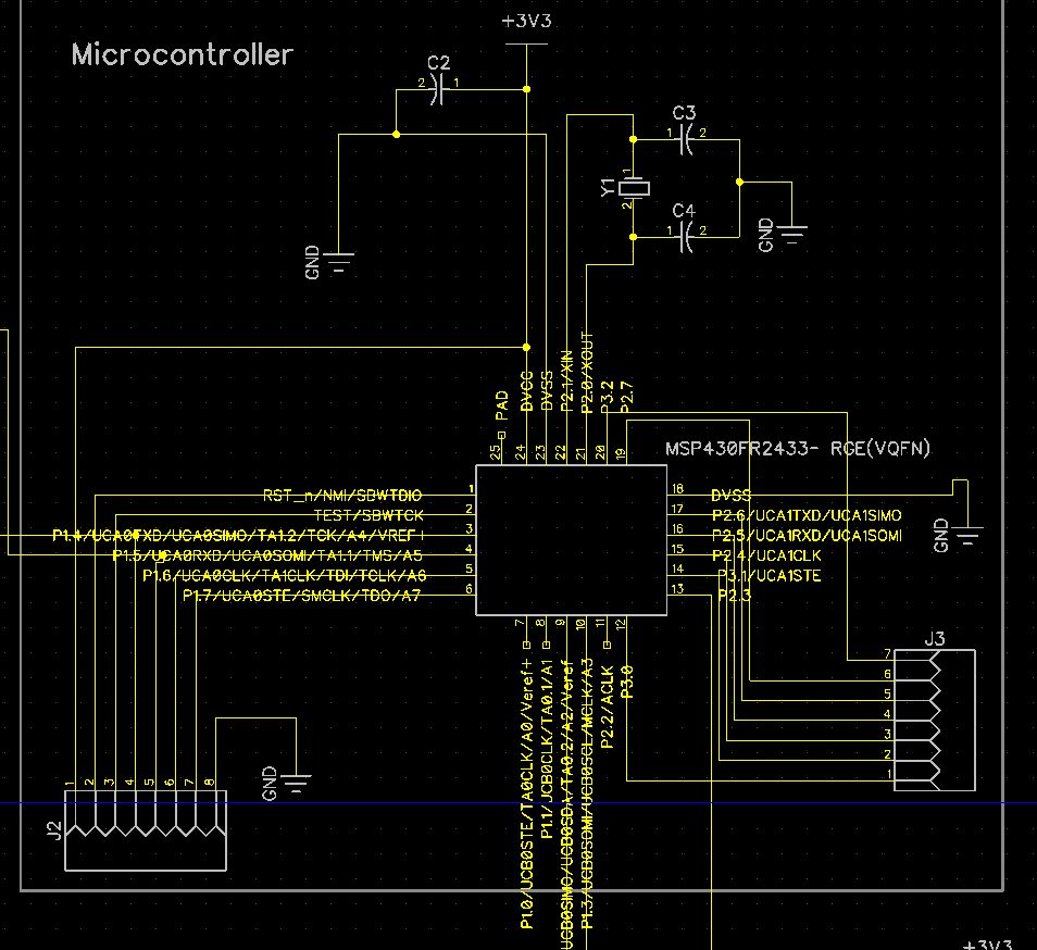
I am attaching the schematic of my circuit.

I have tried programming using Energia & Uniflash both.

Note: I do not have any pullup on SBW lines.

  • Hi Anurag,

    You need pullup a 47K Res in RST pin.

    Best Regards

    Johnson

  • Hello 

    I'm trying to do the same thing here. I made my prototype on the dev board and now I want to make a custom board that only has components needed for my project. I have the following components:

    msp430fr2433

    LCD screen with SPI interface

    Keypad

    Modem with UART interface

    On my board, I need msp430fr2433 to connect to my laptop so that I can put the firmware on it. I went through the docs and see that the Boatloaded works via another micro called msp430F5528. I drew up a rough circuit of how my board should look like. Not kidding about the rough part. Could you please let me know if I'm right? 


    On the schematic which Anurag attached, I don't see an msp430F5528. But I do see the UART lines of msp430fr2433 go outside the picture. I'm assuming they are going to msp430F5528. Could you correct me please Anurag?

    Thank you 

    Varun R 

  • The F5528 "ezFET" chip does give you access to the BSL pins (you need both Tx and Rx) but it doesn't give you direct access to the SBW pins, which you need in order to put your target into BSL mode.

    Given (1) that you need access to the SBW pins in either case and (2) the SBW programmer (in the F5528) provides much higher function than the BSL, I suggest you not use the BSL but rather just connect the Launchpad SBW pins (J101 USB side) to your target's SBW pins and program the target the way have have been doing it.

  • Bruce McKenney47378 said:
    you need both Tx and Rx)

    But Bruce, When I try to put the code on the launchpad, I only have Rx connect via jumped. Tx is not connected. It still works. I did this because I use SPI0 to communicate with an LCD. It's not a problem though, I can use jumpers and make these two lines multifunctional. 

    I understand. I have changed the schematic as you asked and attached it. Please let me know if this is what you were suggesting. If it is, then I'll start working on the actually schematic. 

    Also, I just want to make sure I'm understanding this right. This is what I'm thinking:

    Data comes in from USB (D+ and D-) lines. They are connected to 50 and 52 of mspF5528. Then 43 and 44 of mspF5528 are connected to SBW TDIO and TCK of msp430fr2433 via J101. These put the micro in Bootloader mode. Data is transferred via 37 and 38 which are data in and data out for (SPI and I2C) mspf5528 and is connected to BCL Tx and Rx of msp430Fr2433. Am I right? or at least close.

    Note: Although not included on the rough schematic, I'll have the protective diode and Linear voltage regulator on my custom board. The circuit will be exactly the same. I am removing the MSP102 (micro for energy trace) and IC103(Mux) since I don't need them. 

    Thank you 

    Varun R

  • Using the BSL [Ref FR2 BSL User Guide (SLAU550Z)] requires both Tx and Rx, since it's a bi-directional  protocol. SBW (Spi-Bi-Wire) doesn't require Tx or Rx. SBW is the usual way of loading code in a Launchpad; among other things, SBW provides debug capability and the BSL doesn't.

    It's not clear to me what your goal is. I.e. what would you like to have/do when you're finished?

    Your schematic appears to have re-created the ezFET (the USB side of any Launchpad). If that is your goal, one thing to watch out for -- it used to be that the code that runs on the ezFET controller (F5528) isn't available, so you would have to write your own.

  • Bruce McKenney47378 said:
    it used to be that the code that runs on the ezFET controller (F5528) isn't available, so you would have to write your own.

    Oh right. Didn't think of that. Damn it. 

    My goal is to make a simpler version of this launchpad. The launchpad is great but I don't need all the features that come with it. I have a working prototype with the launchpad but I want to make one Board that has all the components that I need and not have wires lose and stuff. 

    I can make the board with msp30FR2433 and other components but that board would be worthless if my firmware is not on it. How can I program my MSP430FR2433 on my custom board with my firmware that I wrote using CCS? 

    Varun R

  • Johnson He said:

    You need pullup a 47K Res in RST pin.

    FRAM devices are with internal pull-up on RST pin, so device should start-up without external components on RST pin. SBW works best without anything connected to device RST pin (with connected cap signal is "fighting" with charging/discharging). 2xx non-FRAM family is without internal pull-up, so external must be used for start-up, but FET should flash it even without it.

    user6202586 said:

    My goal is to make a simpler version of this launchpad. The launchpad is great but I don't need all the features that come with it. I have a working prototype with the launchpad but I want to make one Board that has all the components that I need and not have wires lose and stuff.

    Here is simpler version FET DIY topic...

    https://forum.43oh.com/topic/5530-custom-ezfet-lite/

    If you don't want to use (not DIY frendly) QFN package, there is LQFP MSP430F5529 that is identical to MSP430F5528 (except package).

  • Hello 

    Thank you so much for your response. I read the blog and I see that he made a board that can program other msp430 micros. I kinda get an idea of how to do it as well. While reading the blog and subsequent blogs, I found the following:

    https://www.digikey.com/product-detail/en/texas-instruments/MSP-FET/296-37897-ND/4914406

    Using the above product, will I be able to program my msp430FR2433 on my custom board directly? I rather pay 140$ and get working directly on my application than spend 1 week in developing a board to just program my msp430fr2433 on my board. 

    I don't need to debug. I can do that on launch pad and finalize the code. Then I'll put the final code on the micro using the above product. It will save me helllot of time. Could anyone confirm my understanding?

    Thank you 

    Varun R

  • You can program (and debug) your target board using the Launchpad you already have. The MSP-FET will give you a few extra features that you probably don't need.

    Just connect the SBW (and power) pins from the USB side of the "bridge" header (J101) on your Launchpad to the respective pins of your target board, and run CCS normally.

  • I get it now. Use the launchpad to program target msp430fr2433 on my custom board by directly connecting the SBW pins. I will just disconnect the jumpers that connects it to the msp430fr2433 on the launchpad. 

    I just complicated a simple task. 

    Thank you 

    Varun R

**Attention** This is a public forum