This thread has been locked.

If you have a related question, please click the "Ask a related question" button in the top right corner. The newly created question will be automatically linked to this question.

CCS/MSP430FR2522: I2C Master Slave between TIVA and MSP430

Part Number: MSP430FR2522
Other Parts Discussed in Thread: TM4C129ENCPDT, MSP430FR2422

Tool/software: Code Composer Studio

Hi

We are developing a product where one TM4C129ENCPDT (I2C Master) and 48 chips of MSP430FR2522IPW16 (I2C slaves) need to communicate with each other in I2C master slave configuration.

For MSP430 is there any I2C slave example code to start with? The one example which I got explains I2C Slave using Interrupt. I want to check using Polling method first. 

Any document to understand the I2C slave configuration registers would also be much helpful.

I've used I2C to communicate with sensor modules like RTC, ADC, GPS etc. where I used to follow the timing diagrams represented in the respective datasheets and get the required data.

But in this case, i have to program MSP430 to behave as a I2C slave. I don't know how to do that.

Thank You for your time and support.

  • Hello,

    The Solutions to Common eUSCI and USCI Serial Communication Issues on MSP430™ MCUs app note is a helpful resource for getting started.

    RAGHUL N M said:
    For MSP430 is there any I2C slave example code to start with? The one example which I got explains I2C Slave using Interrupt. I want to check using Polling method first. 

    There are several slave I2C code examples in the TI Resource Explorer inside CCS or on dev.ti.com. Interrupts are preferred over polling, so there may not be a polling code example available. You may find some polling code by searching the forum though.

    https://dev.ti.com/tirex/explore/node?node=AE.U94Ijeuid.QyTEVq8AQ__IOGqZri__LATEST

    RAGHUL N M said:

    Any document to understand the I2C slave configuration registers would also be much helpful.

    I've used I2C to communicate with sensor modules like RTC, ADC, GPS etc. where I used to follow the timing diagrams represented in the respective datasheets and get the required data.

    Refer to the MSP430FR4xx and MSP430FR2xx Family User's Guide and the FR2522 datasheet.

    Regards,

    James

  • Dear James,

    Thank You for the documents. It's really helpful.

    I've already tried the example code that you've mentioned in the link - msp430fr2422_euscib0_i2c_15.c and msp430fr2422_euscib0_i2c_16.c in two separate micro controllers. It worked!

    But it is unidirectional i.e, the master sends the data always and slave receives the data. I want to send some data from master and receive in slave. After collecting some bytes of data, i want to send it back to master. I tried implementing that on my own. But it didn't work. That's why I've asked polling method to understand I2C master slave little bit easier.

    I've modified the same example code to implement my bi directional data transfer. 

    Can anyone guide me where I went wrong?

    Thank You for your time and support.
    /* --COPYRIGHT--,BSD_EX
     * Copyright (c) 2014, Texas Instruments Incorporated
     * All rights reserved.
     *
     * Redistribution and use in source and binary forms, with or without
     * modification, are permitted provided that the following conditions
     * are met:
     *
     * *  Redistributions of source code must retain the above copyright
     *    notice, this list of conditions and the following disclaimer.
     *
     * *  Redistributions in binary form must reproduce the above copyright
     *    notice, this list of conditions and the following disclaimer in the
     *    documentation and/or other materials provided with the distribution.
     *
     * *  Neither the name of Texas Instruments Incorporated nor the names of
     *    its contributors may be used to endorse or promote products derived
     *    from this software without specific prior written permission.
     *
     * THIS SOFTWARE IS PROVIDED BY THE COPYRIGHT HOLDERS AND CONTRIBUTORS "AS IS"
     * AND ANY EXPRESS OR IMPLIED WARRANTIES, INCLUDING, BUT NOT LIMITED TO,
     * THE IMPLIED WARRANTIES OF MERCHANTABILITY AND FITNESS FOR A PARTICULAR
     * PURPOSE ARE DISCLAIMED. IN NO EVENT SHALL THE COPYRIGHT OWNER OR
     * CONTRIBUTORS BE LIABLE FOR ANY DIRECT, INDIRECT, INCIDENTAL, SPECIAL,
     * EXEMPLARY, OR CONSEQUENTIAL DAMAGES (INCLUDING, BUT NOT LIMITED TO,
     * PROCUREMENT OF SUBSTITUTE GOODS OR SERVICES; LOSS OF USE, DATA, OR PROFITS;
     * OR BUSINESS INTERRUPTION) HOWEVER CAUSED AND ON ANY THEORY OF LIABILITY,
     * WHETHER IN CONTRACT, STRICT LIABILITY, OR TORT (INCLUDING NEGLIGENCE OR
     * OTHERWISE) ARISING IN ANY WAY OUT OF THE USE OF THIS SOFTWARE,
     * EVEN IF ADVISED OF THE POSSIBILITY OF SUCH DAMAGE.
     *
     *******************************************************************************
     *
     *                       MSP430 CODE EXAMPLE DISCLAIMER
     *
     * MSP430 code examples are self-contained low-level programs that typically
     * demonstrate a single peripheral function or device feature in a highly
     * concise manner. For this the code may rely on the device's power-on default
     * register values and settings such as the clock configuration and care must
     * be taken when combining code from several examples to avoid potential side
     * effects. Also see www.ti.com/grace for a GUI- and www.ti.com/msp430ware
     * for an API functional library-approach to peripheral configuration.
     *
     * --/COPYRIGHT--*/
    //******************************************************************************
    //  MSP430FR2422 Demo - eUSCI_B0 I2C Master TX bytes to Multiple Slaves
    //
    //  Description: This demo connects two MSP430's via the I2C bus.
    //  The master transmits to 4 different I2C slave addresses 0x0A,0x0B,0x0C&0x0D.
    //  Each slave address has a specific related data in the array TXData[].
    //  At the end of four I2C transactions the slave address rolls over and begins
    //  again at 0x0A.
    //  ACLK = REFO = 32768Hz, MCLK = SMCLK = default DCO = ~1MHz
    //  Use with MSP430FR2422_uscib0_i2c_16.c
    //
    //                                /|\  /|\
    //               MSP430FR2422      10k  10k     MSP430FR2422
    //                   slave         |    |        master
    //             -----------------   |    |   -----------------
    //            |     P1.2/UCB0SDA|<-|----|->|P1.2/UCB0SDA     |
    //            |                 |  |       |                 |
    //            |                 |  |       |                 |
    //            |     P1.3/UCB0SCL|<-|------>|P1.3/UCB0SCL     |
    //            |                 |          |                 |
    //
    //  Ling Zhu
    //  Texas Instruments Inc.
    //  May 2017
    //  Built with IAR Embedded Workbench v6.50 & Code Composer Studio v7.0.0
    //******************************************************************************
    
    #include <msp430.h>
    
    unsigned char TXData[]= {0xA1,0xB1,0xC1,0xD1};        // Pointer to TX data
    unsigned char SlaveAddress[]= {0x0A,0x0B,0x0C,0x0D};
    unsigned char TXByteCtr;
    unsigned char SlaveFlag = 0;
    volatile unsigned char RXData;
    
    int main(void)
    {
        WDTCTL = WDTPW | WDTHOLD;                         // Stop watchdog timer
    
        // Configure Pins for I2C
        P1SEL0 |= BIT2 | BIT3;                            // I2C pins
    
        // Disable the GPIO power-on default high-impedance mode
        // to activate previously configured port settings
        PM5CTL0 &= ~LOCKLPM5;
    
        // Configure USCI_B0 for I2C mode
        UCB0CTLW0 |= UCSWRST;                             // put eUSCI_B in reset state
        UCB0CTLW0 |= UCMODE_3 | UCMST;                    // I2C master mode, SMCLK
        UCB0BRW = 0x8;                                    // baudrate = SMCLK / 8
        UCB0CTLW0 &=~ UCSWRST;                            // clear reset register
        UCB0IE |= UCRXIE | UCTXIE0 | UCNACKIE;                     // receive , transmit and NACK interrupt enable
    
        SlaveFlag =0;
    
        while(1)
        {
        __delay_cycles(1000);                             // Delay between transmissions
        //UCB0I2CSA = SlaveAddress[SlaveFlag];              // configure slave address
        UCB0I2CSA = SlaveAddress[0];                        // keeping the slave address as constant
        TXByteCtr = 1;                                    // Load TX byte counter
        while (UCB0CTLW0 & UCTXSTP);                      // Ensure stop condition got sent
        UCB0CTLW0 |= UCTR | UCTXSTT;                      // I2C TX, start condition
    
        __bis_SR_register(LPM0_bits | GIE);               // Enter LPM0 w/ interrupts
                                                          // Remain in LPM0 until all data
                                                          // is TX'd
        // Change Slave address
        SlaveFlag++;
        if (SlaveFlag>3)                                  // When all the 4 bytes are sent, putting the I2C in receive mode, sending a start signal and going to LPM
          {
            SlaveFlag =0;
            UCB0CTLW0 &= ~UCTR;  // putting the I2C in receive mode
            UCB0CTLW0 |= UCTXSTT;                      //  sending a start signal
            __bis_SR_register(LPM0_bits | GIE);               // Enter LPM0 w/ interrupts
          }
        }
    
    }
    
    #if defined(__TI_COMPILER_VERSION__) || defined(__IAR_SYSTEMS_ICC__)
    #pragma vector = USCI_B0_VECTOR
    __interrupt void USCIB0_ISR(void)
    #elif defined(__GNUC__)
    void __attribute__ ((interrupt(USCI_B0_VECTOR))) USCIB0_ISR (void)
    #else
    #error Compiler not supported!
    #endif
    {
      switch(__even_in_range(UCB0IV,USCI_I2C_UCBIT9IFG))
      {
            case USCI_NONE: break;                        // Vector 0: No interrupts break;
            case USCI_I2C_UCALIFG: break;
            case USCI_I2C_UCNACKIFG:
                UCB0CTL1 |= UCTXSTT;                      //resend start if NACK
              break;                                      // Vector 4: NACKIFG break;
            case USCI_I2C_UCSTTIFG: break;                // Vector 6: STTIFG break;
            case USCI_I2C_UCSTPIFG: break;                // Vector 8: STPIFG break;
            case USCI_I2C_UCRXIFG3: break;                // Vector 10: RXIFG3 break;
            case USCI_I2C_UCTXIFG3: break;                // Vector 14: TXIFG3 break;
            case USCI_I2C_UCRXIFG2: break;                // Vector 16: RXIFG2 break;
            case USCI_I2C_UCTXIFG2: break;                // Vector 18: TXIFG2 break;
            case USCI_I2C_UCRXIFG1: break;                // Vector 20: RXIFG1 break;
            case USCI_I2C_UCTXIFG1: break;                // Vector 22: TXIFG1 break;
            case USCI_I2C_UCRXIFG0:                         // On receive interrupt, collecting the data from UCB0RXBUF exiting the LPM0
                RXData = UCB0RXBUF;
                __bic_SR_register_on_exit(LPM0_bits);     // Exit LPM0
                break;                // Vector 24: RXIFG0 break;
            case USCI_I2C_UCTXIFG0:
            if (TXByteCtr)                                // Check TX byte counter
               {
                UCB0TXBUF = TXData[SlaveFlag];            // Load TX buffer
                TXByteCtr--;                              // Decrement TX byte counter
               }
            else
               {
                UCB0CTLW0 |= UCTXSTP;                     // I2C stop condition
                UCB0IFG &= ~UCTXIFG;                      // Clear USCI_B0 TX int flag
                __bic_SR_register_on_exit(LPM0_bits);     // Exit LPM0
               }
              break;                                      // Vector 26: TXIFG0 break;
            case USCI_I2C_UCBCNTIFG: break;               // Vector 28: BCNTIFG
            case USCI_I2C_UCCLTOIFG: break;               // Vector 30: clock low timeout
            case USCI_I2C_UCBIT9IFG: break;               // Vector 32: 9th bit
            default: break;
      }
    }
    
    /* --COPYRIGHT--,BSD_EX
     * Copyright (c) 2014, Texas Instruments Incorporated
     * All rights reserved.
     *
     * Redistribution and use in source and binary forms, with or without
     * modification, are permitted provided that the following conditions
     * are met:
     *
     * *  Redistributions of source code must retain the above copyright
     *    notice, this list of conditions and the following disclaimer.
     *
     * *  Redistributions in binary form must reproduce the above copyright
     *    notice, this list of conditions and the following disclaimer in the
     *    documentation and/or other materials provided with the distribution.
     *
     * *  Neither the name of Texas Instruments Incorporated nor the names of
     *    its contributors may be used to endorse or promote products derived
     *    from this software without specific prior written permission.
     *
     * THIS SOFTWARE IS PROVIDED BY THE COPYRIGHT HOLDERS AND CONTRIBUTORS "AS IS"
     * AND ANY EXPRESS OR IMPLIED WARRANTIES, INCLUDING, BUT NOT LIMITED TO,
     * THE IMPLIED WARRANTIES OF MERCHANTABILITY AND FITNESS FOR A PARTICULAR
     * PURPOSE ARE DISCLAIMED. IN NO EVENT SHALL THE COPYRIGHT OWNER OR
     * CONTRIBUTORS BE LIABLE FOR ANY DIRECT, INDIRECT, INCIDENTAL, SPECIAL,
     * EXEMPLARY, OR CONSEQUENTIAL DAMAGES (INCLUDING, BUT NOT LIMITED TO,
     * PROCUREMENT OF SUBSTITUTE GOODS OR SERVICES; LOSS OF USE, DATA, OR PROFITS;
     * OR BUSINESS INTERRUPTION) HOWEVER CAUSED AND ON ANY THEORY OF LIABILITY,
     * WHETHER IN CONTRACT, STRICT LIABILITY, OR TORT (INCLUDING NEGLIGENCE OR
     * OTHERWISE) ARISING IN ANY WAY OUT OF THE USE OF THIS SOFTWARE,
     * EVEN IF ADVISED OF THE POSSIBILITY OF SUCH DAMAGE.
     *
     *******************************************************************************
     *
     *                       MSP430 CODE EXAMPLE DISCLAIMER
     *
     * MSP430 code examples are self-contained low-level programs that typically
     * demonstrate a single peripheral function or device feature in a highly
     * concise manner. For this the code may rely on the device's power-on default
     * register values and settings such as the clock configuration and care must
     * be taken when combining code from several examples to avoid potential side
     * effects. Also see www.ti.com/grace for a GUI- and www.ti.com/msp430ware
     * for an API functional library-approach to peripheral configuration.
     *
     * --/COPYRIGHT--*/
    //******************************************************************************
    //  MSP430FR2422 Demo - eUSCI_B0 I2C 4 Hardware I2C slaves
    //
    //  Description: This demo connects two MSP430's via the I2C bus.
    //  This code configures the MSP430 USCI to be addressed as 4 independent I2C
    //  slaves. Each slave has its own interrupt flag and data variable to store
    //  incoming data.
    //  Use with MSP430FR2422_uscib0_i2c_15.c
    //  ACLK = REFO = 32768Hz, MCLK = SMCLK = default  = DCO = ~1MHz
    //
    //                                /|\  /|\
    //               MSP430FR2422      10k  10k     MSP430FR2422
    //                   slave         |    |        master
    //             -----------------   |    |   -----------------
    //            |     P1.2/UCB0SDA|<-|----|->|P1.2/UCB0SDA     |
    //            |                 |  |       |                 |
    //            |                 |  |       |                 |
    //            |     P1.3/UCB0SCL|<-|------>|P1.3/UCB0SCL     |
    //            |                 |          |                 |
    //
    //  Ling Zhu
    //  Texas Instruments Inc.
    //  May 2017
    //  Built with IAR Embedded Workbench v6.50 & Code Composer Studio v7.0.0
    //******************************************************************************
    
    #include <msp430.h>
    
    unsigned char RXData0=0;
    unsigned char RXData1=0;
    unsigned char RXData2=0;
    unsigned char RXData3=0;
    
    int main(void)
    {
        WDTCTL = WDTPW | WDTHOLD;                             // Stop watchdog timer
    
        // Configure Pins for I2C
        P1SEL0 |= BIT2 | BIT3;                                // I2C pins
    
        // Disable the GPIO power-on default high-impedance mode
        // to activate previously configured port settings
        PM5CTL0 &= ~LOCKLPM5;
    
        // Configure USCI_B0 for I2C mode
        UCB0CTLW0 |= UCSWRST;                                 //Software reset enabled
        UCB0CTLW0 |= UCMODE_3;                                //I2C slave mode, SMCLK
        UCB0I2COA0 = 0x0A | UCOAEN;                           //SLAVE0 own address is 0x0A| enable
        UCB0I2COA1 = 0x0B | UCOAEN;                           //SLAVE1 own address is 0x0B| enable
        UCB0I2COA2 = 0x0C | UCOAEN;                           //SLAVE2 own address is 0x0C| enable
        UCB0I2COA3 = 0x0D | UCOAEN;                           //SLAVE3 own address is 0x0D| enable
        UCB0CTLW0 &=~UCSWRST;                                 //clear reset register
    
        //UCB0IE |=  UCRXIE0 | UCRXIE1| UCRXIE2 | UCRXIE3;      //receive interrupt enable
        UCB0IE |=  UCTXIE0 | UCRXIE0 | UCRXIE1| UCRXIE2 | UCRXIE3;      //transmit , receive interrupt enable
    
        __bis_SR_register(LPM0_bits | GIE);                   // Enter LPM0 w/ interrupts
        __no_operation();
    }
    
    #if defined(__TI_COMPILER_VERSION__) || defined(__IAR_SYSTEMS_ICC__)
    #pragma vector = USCI_B0_VECTOR
    __interrupt void USCIB0_ISR(void)
    #elif defined(__GNUC__)
    void __attribute__ ((interrupt(USCI_B0_VECTOR))) USCIB0_ISR (void)
    #else
    #error Compiler not supported!
    #endif
    {
       switch(__even_in_range(UCB0IV,USCI_I2C_UCBIT9IFG))
        {
          case USCI_NONE: break;                                   // Vector 0: No interrupts break;
          case USCI_I2C_UCALIFG: break;                                   // Vector 2: ALIFG break;
          case USCI_I2C_UCNACKIFG: break;                                   // Vector 4: NACKIFG break;
          case USCI_I2C_UCSTTIFG: break;                                   // Vector 6: STTIFG break;
          case USCI_I2C_UCSTPIFG: break;                                   // Vector 8: STPIFG break;
          case USCI_I2C_UCRXIFG3:                                          // SLAVE3
            RXData3 = UCB0RXBUF;
            break;                                            // Vector 10: RXIFG3 break;
          case USCI_I2C_UCTXIFG3: break;                                   // Vector 14: TXIFG3 break;
          case USCI_I2C_UCRXIFG2:                                          // SLAVE2
            RXData2 = UCB0RXBUF;
            break;                                            // Vector 16: RXIFG2 break;
          case USCI_I2C_UCTXIFG2: break;                                   // Vector 18: TXIFG2 break;
          case USCI_I2C_UCRXIFG1:                                          // SLAVE1
            RXData1 = UCB0RXBUF;
            break;                                            // Vector 20: RXIFG1 break;
          case USCI_I2C_UCTXIFG1: break;                                   // Vector 22: TXIFG1 break;
          case USCI_I2C_UCRXIFG0:                                          // SLAVE0
            RXData0 = UCB0RXBUF;                              // Get RX data
            if(RXData0 == 0xD1) { UCB0TXBUF = 0xE1; }          // 0xD1 is the last data I'm sending from master. On receiving that, I'm sending back 0xE1 to slave.
                                                               // On the master side, when the 4th byte (0xD1) is sent, the master goes to receive mode.
            break;                                            // Vector 24: RXIFG0 break;
          case USCI_I2C_UCTXIFG0: break;                                   // Vector 26: TXIFG0 break;
          case USCI_I2C_UCBCNTIFG: break;                                   // Vector 28: BCNTIFG break;
          case USCI_I2C_UCCLTOIFG: break;                                   // Vector 30: clock low timeout break;
          case USCI_I2C_UCBIT9IFG: break;                                   // Vector 32: 9th bit break;
          default: break;
        }
    
    }


  • Hi

    I tried to edit the example code to make them work without interrupts.

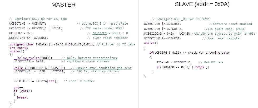
    In the image below are two example codes - Master sends four bytes of data (0xA0,0xB0,0xC0,0xD1) - to slave . When slave receives the last byte of data (0xD1) it breaks from receiving the data. After this the slave has to send the data back to the master i.e, the master has to request 4 bytes of data from the slave and gets it. 

    I don't know how to do that. Should I need to send any dummy clock pulse? How to configure slave to understand that the master is requesting the data and make it respond to it? I've also attached this snippet in text file.

    Thank You for your time

    MASTER CODE:
        
    // Configure USCI_B0 for I2C mode
        UCB0CTLW0 |= UCSWRST;                 // put eUSCI_B in reset state
        UCB0CTLW0 |= UCMODE_3 | UCMST;          // I2C master mode, SMCLK
        UCB0BRW = 0x8;                              // baudrate = SMCLK / 8
        UCB0CTLW0 &=~ UCSWRST;                      // clear reset register
    
        unsigned char TXData[]= {0xA0,0xB0,0xC0,0xD1}; // Pointer to TX data
        Int cnt=0;
        while(1)
        {
        	__delay_cycles(1000);     // Delay between transmissions
        	UCB0I2CSA = 0x0A;         // configure slave address
                                            
        	while (UCB0CTLW0 & UCTXSTP);   // Ensure stop condition got sent
        	UCB0CTLW0 |= UCTR | UCTXSTT;   // I2C TX, start condition
    
    
    	UCB0TXBUF = TXData[cnt];   // Load TX buffer	
    
        	cnt++;
        	if (cnt>3)                                  
          	{
            break;
          }
        }
    
    
    SLAVE CODE:
    
        // Configure USCI_B0 for I2C mode
    UCB0CTLW0 |= UCSWRST;                //Software reset enabled
    UCB0CTLW0 |= UCMODE_3;            //I2C slave mode, SMCLK
    UCB0I2COA0 = 0x0A | UCOAEN;//SLAVE0 own address is 0x0A| enable
    UCB0CTLW0 &=~UCSWRST;            //clear reset register    
    while(1)
    {
       if(UCB0IFG & 0x01) // check for incoming data
       {
           RXData0 = UCB0RXBUF;    // Get RX data
           if(RXData0 == 0xD1) { break ;}
        }
    }
    

**Attention** This is a public forum