Because of the holidays, TI E2E™ design support forum responses will be delayed from Dec. 25 through Jan. 2. Thank you for your patience.

This thread has been locked.

If you have a related question, please click the "Ask a related question" button in the top right corner. The newly created question will be automatically linked to this question.

MSP430G2553: [ISSUE!!] Using MSP430 Timer1_A3 in UP/DOWN mode for PWM control of Half-Bridge Inverter

Part Number: MSP430G2553

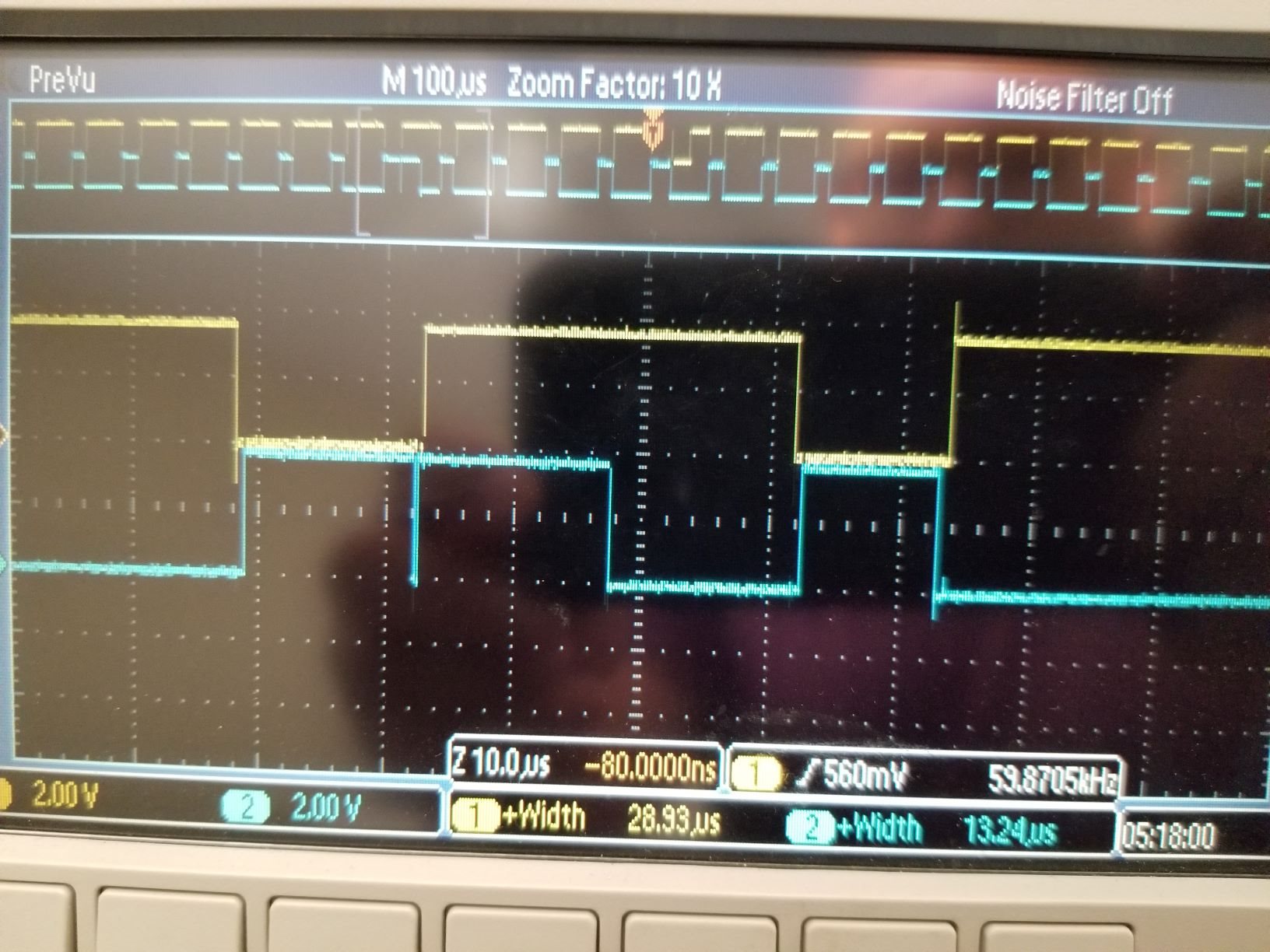
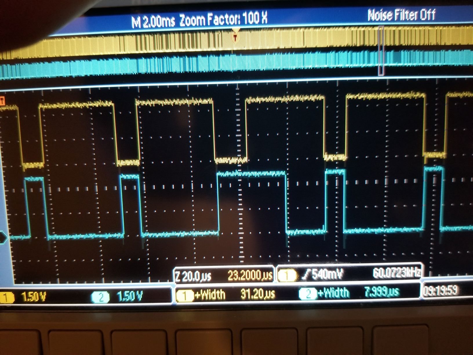
I am using the MSP430G2553 to control the switching of a half-bridge inverter, using Timer1 A3 in up/down mode. However, I am noticing that occasionally the output will either stay on or falsely turn on causing shoot through in my system. I am operating with a DCO of 8 MHz, and I am updating the TA1CCRx using a timer interrupt. Below is an oscilloscope capture of 1 occurrence. Below is also a snippet of the code used. Need assistance to resolve this issue.

#define MCU_CLOCK = 8000000;       // MCU Clock Frequency [8 MHz]
int SW_Freq = 160;                 // MCU Switching Period [MCU CLOCK/SW Freq] [25 kHz]
unsigned int  n = 0;               // Lookup Table array index
unsigned int z = 0;                // Counter
int DUTY_1 = 80;
int DUTY_2 = 75;

/*** SINE WAVE LOOKUP TABLE ***/

static const unsigned int Sin_lookup[84] =
{ 80,  83,  87,  90,  93,  96, 100, 103, 105, 108,
 111, 113, 115, 117, 119, 121, 122, 123, 124, 124,
 125, 125, 125, 124, 124, 123, 121, 120, 118, 117,
 115, 112, 110, 107, 104, 102,  99,  95,  92,  89,
  85,  82,  79,  75,  72,  69,  65,  62,  59,  56,
  54,  51,  48,  46,  44,  42,  40,  39,  38,  37,
  36,  35,  35,  35,  35,  36,  37,  38,  39,  40,
  42,  44,  46,  48,  51,  54,  56,  59,  62,  65,
  69,  72,  75,  79};


/**********************************************/
/*                   main.c
 **********************************************/

void main(void)
{
    WDTCTL = WDTPW | WDTHOLD;       // stop watchdog timer
    DCOCTL = 0;                     // Select lowest DCOx and MODx
    BCSCTL1 = CALBC1_8MHZ;          // Set range
    DCOCTL = CALDCO_8MHZ;           // Set DCO step + modulation

/*** GPIO SETUP ***/

    P2DIR |= BIT2;                  // Set P2.3 as output [TA1.3]
    P2SEL |= BIT2;                  // Select P2.2 for special fcn Timer A3
    P2SEL2 &= ~BIT2;                // Select P2.2 for special fcn Timer A3
    P2DIR |= BIT4;                  // Select P2.4 as Output
    P2SEL |= BIT4;                  // Select P2.4 for special fcn Timer A3
    P2SEL2 &= ~BIT4;                // Select P2.4 for special fcn Timer A3
    P1DIR &= ~BIT1;                 // Set P1.1 as input [A1]
    P1SEL &= ~BIT1;                 // Select P1.1 for general I/O [A1]
    P1SEL2 &= ~BIT1;                // Select P1.1 for general I/O [A1]

/*** Timer A1 SETUP ***/
    TA1CCR0 = SW_Freq-1;              // PWM Control Period
    //TA1CCTL0 |= CCIE;
    TA1CCTL1 |= OUTMOD_6;           // TA1CCR1 output mode = Toggle/Set
    TA1CCTL2 |= OUTMOD_2;           // TA1CCR2 output mode = Toggle/Reset
    TA1CCR1 = DUTY_1;               // TA1CCR1 initial PWM Duty Cycle
    TA1CCR2 = DUTY_2;               // TA1CCR2 initial PWM Duty Cycle
    TA1CTL |= TASSEL_2 + ID_0 + MC_3 + TAIE;      // SMCLK, Divided by 1, Up/Down Mode (Counts to TA1CCR0), & enable interrupts
    _BIS_SR (CPUOFF + GIE);         // Enter LPM0 + enable global interrupts
    while (1);                          // Endless loop
}

/*** Timer_1_A3 Interrupt Service Routine ***/
#pragma vector =unused_interrupts
__interrupt void Timer1_A3_ISR (void)
{

    z++;                                // Increment Counter
    if (z == 5)                         // Counter z == 5, (~200 us); 5 sawtooth cycles, (320 *5) @ 8 MHz
    {
        n++;                            // increment look-up table index
        if (n >=84)                     // check if index value is outside array length
        {n=0;}                          // If true, reset index value
        DUTY_1 = Sin_lookup[n];         // Change look-up table value
        DUTY_2 = Sin_lookup[n]-15;       // Change look-up table value - ~600 ns dead time
        TA1CCR2 = DUTY_2;               // TA1CCR1 PWM Duty Cycle updates
        TA1CCR1 = DUTY_1;               // TA1CCR2 PWM Duty Cycle updates
        z = 0;                          // Reset counter
    }
    TA1CTL &= ~TAIFG;                   // Clear interrupt flag
}

  • From the manual:  "It is recommended to stop the timer before modifying its operation (with exception of the
    interrupt enable, and interrupt flag) to avoid errant operating conditions."

  • I have included stoppage of the timer, however I am still seeing unwanted behavior. Below is the updated interrupt code. Is this a common issue when operating the G2553 at higher than 1 MHz DCO clock?

    /*** Timer_1_A3 Interrupt Service Routine ***/
    #pragma vector =unused_interrupts
    __interrupt void Timer1_A3_ISR (void)
    {
        z++;                                // Increment Counter
        if (z == 5)                         // Counter z == 5, (~200 us); 5 sawtooth cycles, (320 *5) @ 8 MHz
        {
            TA1CTL |= MC_0 + TACLR;         // Stops Timer 1 A3 and clears timer
            n++;                            // increment look-up table index
            if (n >=84)                     // check if index value is outside array length
            {n=0;}                          // If true, reset index value
            DUTY_1 = Sin_lookup[n];         // Change look-up table value
            DUTY_2 = Sin_lookup[n]-5;       // Change look-up table value - ~600 ns dead time
            TA1CCR2 = DUTY_2;               // TA1CCR1 PWM Duty Cycle updates
            TA1CCR1 = DUTY_1;               // TA1CCR2 PWM Duty Cycle updates
            TA1CTL |= TASSEL_2 + ID_0 + MC_3 + TAIE;      // SMCLK, Divided by 1, Up/Down Mode (Counts to TA1CCR0), & enable interrupts
            z = 0;                          // Reset counter
        }
        TA1CTL &= ~TAIFG;                   // Clear interrupt flag
    }

  • Attached is an oscilloscope capture with the updated code.

  • Is there some reason why you don't use TA1IV to verify that you have a valid interrupt and clear it?

    I suspect that the original code had a race condition. For small values from the sine lookup table the counter could pass that value before you updated the registers. Or conversely it could toggle based on the old value before you set the new one. A hazard when running the timer at such a high clock speed.

  • Thanks for the help David, I am unsure in how to implement that using the TA1IV. Would I use a switch() fcn. I am currently using a #pragma vector= unused interrupts because I could not find a interrupt service routine for Timer 1 A3. Could you provide an example if possible. I would greatly appreciate it.

  • After looking further into the family guide I believe I may have figured out the interrupt check using TA1IV. The code is shown below. I will try this out and see if it makes a difference.

    /*** Timer_1_A3 Interrupt Service Routine ***/
    #pragma vector =unused_interrupts
    __interrupt void Timer1_A3_ISR (void)
    {
     switch (TA1IV)
     {
      case TA1IV_NONE:
          break;
      case TA1IV_TACCR1:
          break;
      case TA1IV_TACCR2:
          break;
      case TA1IV_TAIFG:                                 // Interrupt due to Timer overflow interrupt flag
      {
          z++;                                // Increment Counter
          if (z == 5)                         // Counter z == 5, (~200 us); 5 sawtooth cycles, (320 *5) @ 8 MHz
              {
               TA1CTL |= MC_0 + TACLR;         // Stops Timer 1 A3 and clears timer
               n++;                            // increment look-up table index
               if (n >=84)                     // check if index value is outside array length
                 {n=0;}                          // If true, reset index value
               DUTY_1 = Sin_lookup[n];         // Change look-up table value
               DUTY_2 = Sin_lookup[n]-5;       // Change look-up table value - ~600 ns dead time
               TA1CCR2 = DUTY_2;               // TA1CCR1 PWM Duty Cycle updates
               TA1CCR1 = DUTY_1;               // TA1CCR2 PWM Duty Cycle updates
               TA1CTL |= TASSEL_2 + ID_0 + MC_3 + TAIE;      // SMCLK, Divided by 1, Up/Down Mode (Counts to TA1CCR0), & enable interrupts
               z = 0;                          // Reset counter
              }
           TA1CTL &= ~TAIFG;                   // Clear interrupt flag
           break;
      }
      default:
           break;
      }
    }

  • >        TA1CTL |= MC_0 + TACLR;         // Stops Timer 1 A3 and clears timer

    This doesn't stop the timer. To do that, you should

    >       TA1CTL = (TA1CTL & ~MC) | TACLR;         // Stops Timer 1 A3 and clears timer

    I'm also not sure you want to use TACLR. Stopping the timer is already going to cause a small aberration in the timing, and resetting the counter will make the aberration that much bigger.

    Also, your goal should be to update the CCR as close to the beginning of the cycle as you can manage. To this end, I suggest you update the CCR as the first thing, and then do your bookkeeping (preparation for next time) afterward, while the counter is counting.

  • I've tried to stop the timer differently, removed the timer clear, and rearranged the order of the lines to prioritize updating CCR. However, I am still getting an undesired output. Attached is the updated interrupt service routine as well as an o-scope image of the output.

    /*** Timer_1_A3 Interrupt Service Routine ***/
    #pragma vector =unused_interrupts
    __interrupt void Timer1_A3_ISR (void)
    {
     switch (TA1IV)
     {
      case TA1IV_NONE:
          break;
      case TA1IV_TACCR1:
          break;
      case TA1IV_TACCR2:
          break;
      case TA1IV_TAIFG:                       // Interrupt due to Timer overflow interrupt flag
      {
          if (z == 5)                         // Counter z == 5, (~200 us); 5 sawtooth cycles, (320 *5) @ 8 MHz
              {
               TA1CTL &= ~MC_3;                // Stops Timer 1 A3 and clears timer
               TA1CTL |= MC_0;                 // Sets TA1CTL to STOP mode (MC_0)
               TA1CCR2 = Sin_lookup[n]-5;               // TA1CCR1 PWM Duty Cycle updates
               TA1CCR1 = Sin_lookup[n];               // TA1CCR2 PWM Duty Cycle updates
               TA1CTL |= TASSEL_2 + ID_0 + MC_3 + TAIE;      // SMCLK, Divided by 1, Up/Down Mode (Counts to TA1CCR0), & enable interrupts
               z = 0;                          // Reset counter
               n++;                            // increment look-up table index
               if (n >=84)                     // check if index value is outside array length
                 {n=0;}                        // If true, reset index value
              }
           z++;                                // Increment Counter
           TA1CTL &= ~TAIFG;                   // Clear interrupt flag
           break;
      }
      default:
           break;
      }
    }
     

  • It looks like you're still losing the race, i.e. by the time you update CCR2, the timer is already past it.

    The smallest value I see in your table is 35, so your deadline for updating CCR2 (or stopping the timer) is 35-5=30 clocks. Estimate 15 clocks to get into the ISR, that gives you 15 clocks to get to the critical step, which is only 3-4 instructions. This timing is very tight.

    1) Try the optimizer, if you haven't already. That might give you back the few extra clocks you need.

    2) I'm going to respectfully disagree with David and say you shouldn't bother to check the IV -- you know why you're here, and it costs you extra CPU clocks in a critical path. Put a comment in a prominent spot at the top to the effect that "TAIFG is the only reason we get here".

    3) Consider dispensing with the interrupt entirely, and poll for TAIFG up in main(). Your entire cycle is only 320 clocks, and you're probably using up half of that in your bookkeeping, i.e. your program won't be able to do much else anyway.

  • The best way to attack this is to slow down the timer clock. Get it working with a slower clock and then work on making it run at the desired rate.

  • Thank you for everyone's assistance with this matter. I changed my DCO to 12 MHz, and then divided it by two, to get a SMCLK of 6 MHz. I have maintained the interrupts to control the change in CCR and I am no longer getting the unintended output from my Timer ports. I had to also change the startup CCR to prevent initail shoot through, but everything seems to work well now.

  • To EE,

    I have run into similar race conditions with a 150kHz analog front end. The best (and only) solution was to increase the frequency of the processor. Even just a double of the frequency will give you twice the processing time you have now, and would  easily solve the race problems.

    Hope this helps.

**Attention** This is a public forum