This thread has been locked.

If you have a related question, please click the "Ask a related question" button in the top right corner. The newly created question will be automatically linked to this question.

MSP430FR6047: Some of the LCD segments not working

Part Number: MSP430FR6047
Other Parts Discussed in Thread: EVM430-FR6047,

Hello,

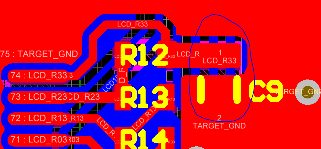
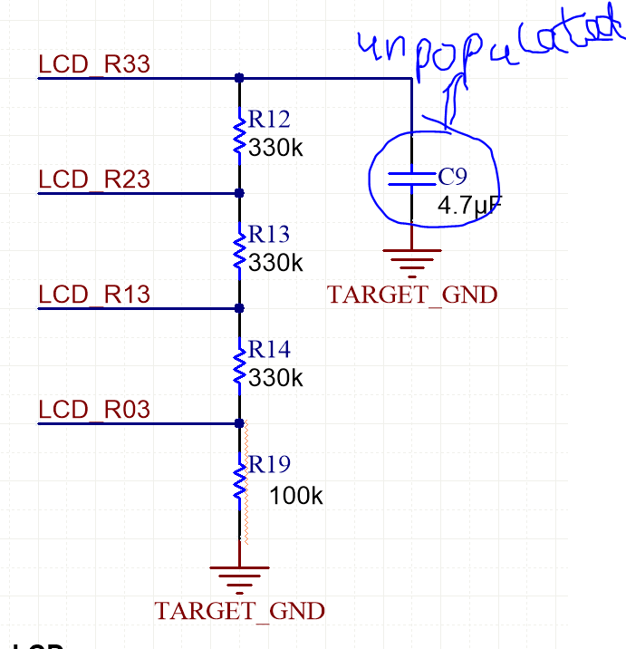
I have built a custom board based on EVM430-FR6047. The LCD I am using is (www.mouser.in/.../825-VIM878DPRCSLV ). Some of the LCD segments dont work in some of the copies of the assembled device. They dont work even after resetting the board. The segments dont work unless reprogrammed.The contrast is perfect but I havent populated the capacitor just like EVM430-FR6047. Could this be creating the issue?

  • Hi, Sagar, 

    What is the COM, and bias for the LCD? 

    If you are using the LCD module internal charge pump to generate the LCD bias voltages, you should connect 4.7uF on the pin LCDCAP./R33.  

    If you are using external resistor divider to generate LCD bias voltages, you should connector resistor on pin LCDCAP/R33 pin. 

    Please refer to the pin description, the section 5.13.9 and 7.2.2.4 in the MSP430FR6047 datasheet for details. There is also detailed description for operation theory and register configuration in user's guide slau367

    Thanks, 

    Lixin 

  • Hello Lixin,

    I am not sure about the bias voltages. How would I be able to check that. I am using a resistor divider with the schematic and code attached. I had tuned the R19 resistor value to set the contrast I require. I am using the default code inititalization as for EVM430-FR6047. I think the internal charge pump is not used. Do you suggest any changes both from schematics and firmware perspective for a stable result? Or some experimentation required?

    void hal_lcd_Init(void)
    {
        LCD_C_initParam initParams = {0};
        initParams.clockSource = LCD_C_CLOCKSOURCE_ACLK;
        initParams.clockDivider = LCD_C_CLOCKDIVIDER_1;
        initParams.clockPrescalar = LCD_C_CLOCKPRESCALAR_16;
        initParams.muxRate = LCD_C_4_MUX;
        initParams.waveforms = LCD_C_LOW_POWER_WAVEFORMS;
        initParams.segments = LCD_C_SEGMENTS_ENABLED;
    
        /*
        * Select Port 6
        * Set Pin [4:7] as LCD COM, [1:3] as R03/R13/R23
        */
    #ifdef LCD_USE_RES_LADDER
        GPIO_setAsPeripheralModuleFunctionInputPin(
            GPIO_PORT_P6,
            GPIO_PIN4 | GPIO_PIN5 | GPIO_PIN6 | GPIO_PIN7 | GPIO_PIN1 | GPIO_PIN2 | GPIO_PIN3,
            GPIO_TERNARY_MODULE_FUNCTION
            );
    #else
        GPIO_setAsPeripheralModuleFunctionInputPin(
            GPIO_PORT_P6,
            GPIO_PIN4 | GPIO_PIN5 | GPIO_PIN6 | GPIO_PIN7,
            GPIO_TERNARY_MODULE_FUNCTION
            );
    #endif
        LCD_C_init(LCD_C_BASE, &initParams);
        // LCD Operation - VLCD generated internally, V2-V4 generated internally, v5 to ground
    
        LCD_C_setPinAsLCDFunctionEx(LCD_C_BASE, LCD_C_SEGMENT_LINE_0,
                                    LCD_C_SEGMENT_LINE_31);
    
    #ifdef LCD_USE_RES_LADDER
        LCD_C_setVLCDSource(LCD_C_BASE,
                            LCD_C_VLCD_GENERATED_INTERNALLY,
                            LCD_C_V2V3V4_GENERATED_INTERNALLY_SWITCHED_TO_PINS,
                            LCD_C_V5_SOURCED_FROM_R03);
    #else
        LCD_C_setVLCDSource(LCD_C_BASE,
                            LCD_C_VLCD_GENERATED_INTERNALLY,
                            LCD_C_V2V3V4_GENERATED_INTERNALLY_NOT_SWITCHED_TO_PINS,
                            LCD_C_V5_VSS);
    #endif
    
    #ifdef LCD_USE_CHARGEPUMP
        LCD_C_setVLCDVoltage(LCD_C_BASE,
                            LCD_C_CHARGEPUMP_VOLTAGE_3_02V_OR_2_52VREF);
                            //LCD_C_CHARGEPUMP_VOLTAGE_2_60V_OR_2_17VREF);
                            //LCD_C_CHARGEPUMP_VOLTAGE_3_44V_OR_2_87VREF);
        // Enable charge pump and select internal reference for it
        LCD_C_enableChargePump(LCD_C_BASE);
        LCD_C_selectChargePumpReference(LCD_C_BASE,
                                        LCD_C_INTERNAL_REFERENCE_VOLTAGE);
    #else
        LCD_C_setVLCDVoltage(LCD_C_BASE,
                            LCD_C_CHARGEPUMP_DISABLED);
        LCD_C_disableChargePump(LCD_C_BASE);
    
    #endif
    
        LCD_C_configChargePump(LCD_C_BASE, LCD_C_SYNCHRONIZATION_ENABLED, 0);
    
        // Clear LCD memory
        LCD_C_clearMemory(LCD_C_BASE);
    
        //Turn LCD on
        LCD_C_on(LCD_C_BASE);
    }

  • Hi, 

    Bias voltages are the different voltage levels on the LCD signals. In the LCD chapter of user's guide slau367, you can find the LCD signals as following figure for 4COM LCD. 

    You can measure the voltages on the LCD pins or the 4 pins R03/R13/R23/R33 to check if the voltage levels are meeting the LCD specification. 

    From the code, you are using the define micro to enable the charge pump or use the resistor divider to generate the bias voltages. You can also try to use both ways to generate the bias voltages to see which is correct.

    The EVM hardware files and source code are good example. User's guide slau367 has detailed information about the LCD operation and configuration. Please study the materials to find solution for your issues. 

    Thanks, 

    Lixin

  • Hello,

    Yes I am trying to understand in a better way. Kindly explain the two statements its unclear to me.

    Regards,
    Prudhvi Sagar

  • Hi, 

    This is the register LCDREXT description. 

    When LCDREXT set to 1, internal charge pump will output voltages on V2 to V4. Section 30.2.5.2 in the user's guide has the detailed description. 

  • Hello,

    I am confused with the statement "switched to external pins".

    Regards,

    Prudhvi Sagar

  • There are switches to control the output the V2-V4 to external pins: R13, R23, R33. 

    Thanks, 

    Lixin 

  • Hello,

    So this is used to utilize the Resistor divider to set the bias voltage? Can the internal charge pump and the resistor divider be activated simultaneously. So can the pin R33 be connected to a resistor and a capacitor simultaneously? 

    Regards,

    Prudhvi Sagar

  • Hi, 

    There are 2 options for bias generation: 

    1. Use internal charge pump, with capactor on R33 pin. 

    2. Use external resistor divider. 

    These 2 options cannot be enabled at the same time. 

    So pin R33 cannot be connected to a resistor and a capacitor simultaneously. But for option 2 (resistor divider), the capacitor on R33 may not hurt the bias performance, which works as a de-coupling cap. Then that is fine to have the capacitor. 

    Thanks, 

    Lixin 

  • Hello Lixin,

    Thank you for the quick reply. So to summarize the situation, given V5 is fixed to R03 and no external bias is used it leads to 3 sitautions: (?)

    1. Using Charge pump + Not using Resistor divider.

    2. Not using Charge pump + using Resistor divider.

    3. Not using Charge pump + Not using Resistor divider.

    Kindly confirm. 

    Regards,

    Prudhvi Sagar.

  • Hi, 

    I think your understanding is right. 

    Options 1 and 2 can work for LCD bias generation. Option 3 cannot generate the bias for LCD so that option 3 means no enabled LCD.  

    Thanks, 

    Lixin 

  • Hello Lixin,

    I have tried the 3rd option as attached, it still works. My main issue is on prolonged usage, some of the segments die and do not work on a reset as well. It requires a complete re-program for it to work. Is this an issue which you are already aware of? Why does this happen? I am planning to run the devices with the 3 options and then check which one doesnt die.

    Regards,

    Prudhvi Sagar.

  • Hi, 

    If you are following the EVM board for hardware design for LCD, and also following the EVM code example, it should be no problem for the LCD driving.

    If you have checked the bias voltage and confirmed it is no problem, but LCD segment still has some problem, you need to check other items. 

    You said "Some of the LCD segments don't work in some of the copies of the assembled device. They don't work even after resetting the board. The segments don't work unless reprogrammed". I haven't run into this issue before. Here are some thoughts for you to try to find the root cause. 

    1) When the issue occurs? Do you have the condition to reproduce the issue? It seems the board works well. But with some reason after some time, some LCD segments display abnormally. The issue cannot be resolved by resetting the board. The issue disappears after reprogramming. 

    2) How many boards have you tested? Do all the boards have the issue or just some % of the board have the issue? 

    3) Do you have swapped the MSP430FR6047 between the boards to see if the issue occurs with the MCU or the issue is MCU independent? It seems MCU related because the board works again after reprogramming. 

    4) Could you confirm it is the hardware issue or software issue? From my experience, it is mostly like software issue: user code doesn't load data to these segments, or the LCD driver code is changed for some reason. 

    • For code doesn't load data to these segments, please track the code execution to see if there is some logic wrong in the code. 
    • For the LCD driver code changed, please check if there is code for FRAM write operation. 

    Thanks, 

    Lixin 

**Attention** This is a public forum