This thread has been locked.

If you have a related question, please click the "Ask a related question" button in the top right corner. The newly created question will be automatically linked to this question.

I2C between MSP430F2272 and the Melexis mlx90614

Other Parts Discussed in Thread: MSP430F2272, MSP430F5510, MSP430F5438, MSP430F2274

I am having a really tough time trying to get the I2C to work in the 2272. I meed to use a repeat start but I cant seem to get it to work. Can someone provide some tips on how to send this: S->Slave Address->W->ACL->Data->ACK->S->Slave Address->R->ACK->Data Byte Low->ACK->Data Byte High->ACK->PEC->ACK->STOP

1. Send START bit
2. Send Slave Address (0x00* for example) + Rd\-Wr bit**
3. Send Command (0b000x_xxxx + 0b0000_0111 -> 0b0000_0111)
4. Send Repeated START_bit
5. Send Slave Address + Rd\-Wr bit**
6. Read Data Byte Low (master must send ACK bit)
7. Read Data Byte High (master must send ACK bit)
8. Read PEC (master can send ACK or NACK)
9. Send STOP bit

I have looked at msp430x22x4_uscib0_i2c_12.c   USCI_B0 I2C Master TX/RX multiple bytes from MSP430 Slave with a repeated start

but I dont really understand what is happening. The code for it is:

#include "msp430x22x4.h"

#define NUM_BYTES_TX 3                         // How many bytes?
#define NUM_BYTES_RX 2

int RXByteCtr, RPT_Flag = 0;                // enables repeated start when 1
volatile unsigned char RxBuffer[128];       // Allocate 128 byte of RAM
unsigned char *PTxData;                     // Pointer to TX data
unsigned char *PRxData;                     // Pointer to RX data
unsigned char TXByteCtr, RX = 0;
unsigned char MSData = 0x55;

void Setup_TX(void);
void Setup_RX(void);
void Transmit(void);
void Receive(void);

void main(void)
{
  WDTCTL = WDTPW + WDTHOLD;                 // Stop WDT
  P3SEL |= 0x06;                            // Assign I2C pins to USCI_B0
 
  while(1){
   
  //Transmit process
  Setup_TX();
  RPT_Flag = 1;
  Transmit();
  while (UCB0CTL1 & UCTXSTP);             // Ensure stop condition got sent
 
  //Receive process
  Setup_RX();
  Receive();
  while (UCB0CTL1 & UCTXSTP);             // Ensure stop condition got sent
  }
}

//-------------------------------------------------------------------------------
// The USCI_B0 data ISR is used to move received data from the I2C slave
// to the MSP430 memory. It is structured such that it can be used to receive
// any 2+ number of bytes by pre-loading RXByteCtr with the byte count.
//-------------------------------------------------------------------------------
#pragma vector = USCIAB0TX_VECTOR
__interrupt void USCIAB0TX_ISR(void)
{
  if(RX == 1){                              // Master Recieve?
  RXByteCtr--;                              // Decrement RX byte counter
  if (RXByteCtr)
  {
    *PRxData++ = UCB0RXBUF;                 // Move RX data to address PRxData
  }
  else
  {
    if(RPT_Flag == 0)
        UCB0CTL1 |= UCTXSTP;                // No Repeated Start: stop condition
      if(RPT_Flag == 1){                    // if Repeated Start: do nothing
        RPT_Flag = 0;
      }
    *PRxData = UCB0RXBUF;                   // Move final RX data to PRxData
    __bic_SR_register_on_exit(CPUOFF);      // Exit LPM0
  }}
 
  else{                                     // Master Transmit
      if (TXByteCtr)                        // Check TX byte counter
  {
    UCB0TXBUF = MSData++;                   // Load TX buffer
    TXByteCtr--;                            // Decrement TX byte counter
  }
  else
  {
    if(RPT_Flag == 1){
    RPT_Flag = 0;
    PTxData = &MSData;                      // TX array start address
    TXByteCtr = NUM_BYTES_TX;                  // Load TX byte counter
    __bic_SR_register_on_exit(CPUOFF);
    }
    else{
    UCB0CTL1 |= UCTXSTP;                    // I2C stop condition
    IFG2 &= ~UCB0TXIFG;                     // Clear USCI_B0 TX int flag
    __bic_SR_register_on_exit(CPUOFF);      // Exit LPM0
    }
  }
 }
 
}

void Setup_TX(void){
  _DINT();
  RX = 0;
  IE2 &= ~UCB0RXIE; 
  while (UCB0CTL1 & UCTXSTP);               // Ensure stop condition got sent// Disable RX interrupt
  UCB0CTL1 |= UCSWRST;                      // Enable SW reset
  UCB0CTL0 = UCMST + UCMODE_3 + UCSYNC;     // I2C Master, synchronous mode
  UCB0CTL1 = UCSSEL_2 + UCSWRST;            // Use SMCLK, keep SW reset
  UCB0BR0 = 12;                             // fSCL = SMCLK/12 = ~100kHz
  UCB0BR1 = 0;
  UCB0I2CSA = 0x48;                         // Slave Address is 048h
  UCB0CTL1 &= ~UCSWRST;                     // Clear SW reset, resume operation
  IE2 |= UCB0TXIE;                          // Enable TX interrupt
}
void Setup_RX(void){
  _DINT();
  RX = 1;
  IE2 &= ~UCB0TXIE; 
  UCB0CTL1 |= UCSWRST;                      // Enable SW reset
  UCB0CTL0 = UCMST + UCMODE_3 + UCSYNC;     // I2C Master, synchronous mode
  UCB0CTL1 = UCSSEL_2 + UCSWRST;            // Use SMCLK, keep SW reset
  UCB0BR0 = 12;                             // fSCL = SMCLK/12 = ~100kHz
  UCB0BR1 = 0;
  UCB0I2CSA = 0x48;                         // Slave Address is 048h
  UCB0CTL1 &= ~UCSWRST;                     // Clear SW reset, resume operation
  IE2 |= UCB0RXIE;                          // Enable RX interrupt
}
void Transmit(void){
    PTxData = &MSData;                      // TX array start address
    TXByteCtr = NUM_BYTES_TX;                  // Load TX byte counter
    while (UCB0CTL1 & UCTXSTP);             // Ensure stop condition got sent
    UCB0CTL1 |= UCTR + UCTXSTT;             // I2C TX, start condition
    __bis_SR_register(CPUOFF + GIE);        // Enter LPM0 w/ interrupts
}
void Receive(void){
    PRxData = (unsigned char *)RxBuffer;    // Start of RX buffer
    RXByteCtr = NUM_BYTES_RX-1;              // Load RX byte counter
    while (UCB0CTL1 & UCTXSTP);             // Ensure stop condition got sent
    UCB0CTL1 |= UCTXSTT;                    // I2C start condition
    __bis_SR_register(CPUOFF + GIE);        // Enter LPM0 w/ interrupts
}

  • Steven settle said:
    but I dont really understand what is happening.

    Welcome to the club. :) The examples, while working, have to be digested with care.
    In this case you need to know (it' sin the users guide, but barely detectabel) that in I2C mode, data read and data write are handled by teh TX interrupt while the status changes are handled by the RX interrupt (the USCI module in teh 5x devices does generally handle R and TX and everything in the same interrupt, but has separate interrupts for A and B module instead)

    Since in I2C mode, there' sonly one transfer direction at a given time (either you sen dor you receive) the cause of the interrupt is determined by teh state of several global variables which are initialized by teh start transfer function, rather than by reading the interrupt flags.

    Unlike typical TI code, this one is fairly well decomented. Yet the comments are often stating the obvious, while the 'stategy' behind is still opaque.

    Back to your original problem:

    Most of the detailed protocol you describe is already implemented in hardware. The I2C ducntion you posted are a good example but go far beyond what you need (and are not as flexible as requried).

    1. Send START bit
    2. Send Slave Address (0x00* for example) + Rd\-Wr bit**

    • set the SWRST bit
    • configure the USCI (baudrate etc.)
    • clear the SWRST bit
    • write the slave address (7 bit) to the slave address register
    • set the transmit bit UCTR
    • set the 'send start condition' bit UCTXSTT.
    • the USCI will now generate a start condition, send the slave address and the R/W bit (set)
    • Now the USCI receives teh ACK form teh slave or no ACK if the slave is not responding or is busy and don't want to be bothered :)
    • You'll see the STT bit cleared and either the NACKIFG or TXIFG bit set. NACKIG means no slave was responding, TXIFG means you can now write the command into the TXBUF.

    3. Send Command (0b000x_xxxx + 0b0000_0111 -> 0b0000_0111)
    4. Send Repeated START_bit
    5. Send Slave Address + Rd\-Wr bit**

    • once TXIFG is set again after wrriting the command, you clear the transmit bit and set UCSTT again
    • an repeated start is generated, teh slave address is sent again and the R/W bit (this tiem clear as UCTR was cleared)
    • Once the ACK bit has been received, you'll see STT cleared and either NACKIFG is set (no slave response) or nothign happens. The USCI is now fetching the first byte from the slave.
    • Eventually, RXIFG is set and a byte is ready to be read from RXBUF.
    • If this is the last byte you want, you'll have to set UCSTP bit now.
    • read the byte from RXBUF. The USCI will now send an ACK to the slave, or, if you did set UCSTP, a NACK, followed by a stop condition.
    • If you didn't set UCSTP, wait for the next byte.
    • If you're done, you should wait for UCBBUSY to be clear or UCSTP to be clear, so you knwo that transfer has been finished.

    6. Read Data Byte Low (master must send ACK bit)
    7. Read Data Byte High (master must send ACK bit)
    8. Read PEC (master can send ACK or NACK)
    9. Send STOP bit

    You see, no interrupts required (they are only required if you want do do background transfers, usually sends, and don't need any received data imemdiately. Or if you want to go into low-power mode to consever power during the transfer.

    But for a start, this is straight and fairly simple.

  • This code doesn't work but its closer. When the data is sent is shown on my lsa as 0111(the command) 111110... (no clue why this is there) it should be the command then the ack, then a repeated start, then the slave address...


    #include "msp430f2272.h"

    unsigned char temp_low;
    unsigned char temp_high;
    unsigned char PEC;

    void main(void)
    {
      WDTCTL = WDTPW + WDTHOLD;
      P3SEL |= 0x06; 
      UCB0CTL1 |= UCSWRST;                     
      UCB0CTL0 = UCMST + UCMODE_3 + UCSYNC;  
      UCB0BR0 = 24;                           
      UCB0BR1 = 0; 
      UCB0CTL1 = UCSSEL_2 + UCSWRST;
      UCB0CTL1 &= ~UCSWRST;           
      UCB0I2CSA = 0x00;  
      UCB0CTL1 |= UCTR;
      UCB0CTL1 |= UCTXSTT;
      while (UCB0I2CIE&0x2); //checking UCSTTIE
      UCB0TXBUF = 0x7;
      while (IFG2&0x8);  //checking UCB0TXIFG
      UCB0CTL1 &= ~UCTR;
      UCB0CTL1 |= UCTXSTT;
      while (UCB0I2CIE&0x2); //checking UCSTTIE
      while (~(IFG2&0x4)); //checking ~UCB0RXIFG
      temp_low=UCB0RXBUF;
      while (~(IFG2&0x4)); //checking ~UCB0RXIFG
      temp_high=UCB0RXBUF;
      while (~(IFG2&0x4)); //checking ~UCB0RXIFG
      PEC=UCB0RXBUF;
      UCB0CTL1 |= UCTXSTP;
      while(UCB0STAT&0x10); //checking UCBBUSY
      while(1);
    }

  • I also just realized that no matter what the command is it always looks like 0111(I guess its not the  command) 111110...

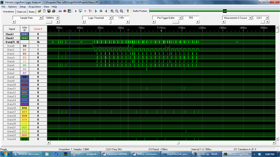
  • Here is a picture

  • Steven settle said:
    UCB0I2CIE&0x2

    Won't work. This bit is set by the user to tell the hardware to trigger an ISR. It does not change unles you change it. IE stands for 'Interrupt Enable'. It's rather the IFG flags in UCB0I2CIFG which have to be tested, if at all.

    Also, UCSTTIFG is only set if you receive a start condition in slave mode.
    The bit to check is the UCTXSTT bit in UCB0CTL1, which is set by you to initiate a start condition, and is cleared by hardware after the start has been sent together with slave address and r/w bit and the response (ACK or NACK) has been received. 

    If there is a NACK, you cannot send anything (of course, since no slave responded to your call) and your while(ifg2&0x08) will stall.

    Also, it's possible that 0x00 is an invalid slave address (just a feeling, or was it the general call? Then you cannot receive anything with this slave address) and that it must be set before clearing SWRST (in your demo code, it i set before, but in your second code, it is set after)

    At least you start getting 'something' on the scope :)

    Unfortunately your screenshot is scaled-down so I cannor really see anything.

  • It is still doing the same thing but here is the new code and a better picture is at the bottom

    #include "msp430f2272.h"

    unsigned char temp_low;
    unsigned char temp_high;
    unsigned char PEC;

    void main(void)
    {
      WDTCTL = WDTPW + WDTHOLD;
      P3SEL |= 0x06; 
      UCB0CTL1 |= UCSWRST;                     
      UCB0CTL0 = UCMST + UCMODE_3 + UCSYNC;  
      UCB0BR0 = 24;                           
      UCB0BR1 = 0; 
      UCB0I2CSA = 0x00;  
      UCB0CTL1 = UCSSEL_2 + UCSWRST;
      UCB0CTL1 &= ~UCSWRST;           
        
      UCB0CTL1 |= UCTR+UCTXSTT;
      UCB0TXBUF = 0x7;
      while (IFG2&UCB0TXIFG);  //checking UCB0TXIFG
      UCB0CTL1 &= ~UCTR;
      IFG2=IFG2&0xFB;
      UCB0CTL1 |= UCTXSTT;
      while (IFG2&UCB0TXIFG);
      while (UCB0CTL1 & UCTXSTT);//(IFG2&0x4)); //checking ~UCB0RXIFG
      temp_low=UCB0RXBUF;
      while (UCB0CTL1 & UCTXSTT);//(IFG2&0x4)); //checking ~UCB0RXIFG
      temp_high=UCB0RXBUF;
      while (UCB0CTL1 & UCTXSTT);//(IFG2&0x4)); //checking ~UCB0RXIFG
      PEC=UCB0RXBUF;
      UCB0CTL1 |= UCTXSTP;
      while(UCB0STAT&0x10); //checking UCBBUSY
      while(1);
    }


    http://img806.imageshack.us/img806/9631/lsa.png

  • also according to the datasheet for the device a 0x00 address will work so I know that is not the problem

  • First, when using the general call address (your scope notation indicates that 0x00 is indeed the general call address), you cannot read anything. This is against the I2C specs. You can only write on a GC. It's obvious - addressing all devices on the bus won't select a single one for repsonding - all woudl respond at the same time.

    The SM-Bus (I think) extends the I2C specs and abuses this invalid condition to enumerate all devices on the bus. All devices answer to a GC with their own address, but withdraw as soon as they see that they want to send a '1' bit while someone else sends a '0' bit. This way, teh 'lowest' answer  wins and will not respond again to the same GC. This can be repeated until no more devices respond and you got all addresses. This is, however, not supported in the MSP hardware (the slave mode does not do any bus arbitration checks).

    Anyway, the 'command' should be sent properly. So what happens...

    Steven settle said:
    while (IFG2&UCB0TXIFG);  //checking UCB0TXIFG

    THis is a NOP. You are checking for UCB0TXIFG cleared. But you wrote to TXBUF just a cycle before, so it IS clear (unless you clock the bus with MCLK :) ) You should use while (!(IFG2&UCB0TXIFG));
    Anyway, if there is no ACK form the deice, this flag will never be set but UCNACKIFG instead. you really should check both and exit  Or better, you check for UCSTT being clear again (this means, the address has been sent and either acked or nacked), then check for UCTXIFG being set. If not set, set the UCTXSTP bit and abort. In this case, the command byte will not be sent at all and the TX buffer is cleared.

    Steven settle said:
    IFG2=IFG2&0xFB;

    Why that? Not necessary (see below) Also, you should use ~UCBTXIFG instead of 0xFB as it is clearer (I can only guess that UCBTXIFG is 0x04 without digging into the users guide, and even if I knew, I can only guess that you really meant clearing UCBTXIFG or something else and it is just a typo).

    Steven settle said:
    UCB0CTL1 |= UCTXSTT;

    Since you cleared UCTR, this will immediately clear any pending UCTXIFG. Once again check for UCTXSTT being cleared, then check for UCNACKIFG. If it is set (not likely) abort. If it is clear, wait for UCRXIFG becoming set. Then the first byte has been received.

    before (!) reading the last byte you want from RXBUF, set the UCTXSTP bit.

    I don't understand where the 0x7f comes from in your screendhot. Also, the second byte is 10 bit (including the ACK), which is very strange. There's a clock pulse too much. And a stretched pulse in the middle. That's really weird.

    Then, one of these pulses is stretched. No reason for this. So where does it come from? And before the ACK bit, tehre should be a short high transition when teh master releases the bus and the slave gives its ACK. Like it happens on the address byte.
    Not even teh wrong waits in your code (actualy nothing) should be able to produce this output. It simply makes no sense. It is as if in teh middle of the transmission of the second byte, a second master kicks in and nobody cares for arbitration.

    Also, what does the 0h/1h/2h/3h value mean? I jsu tnothice that these values are different in the second (data) part compared to the (correct) address part. There should be no difference in teh signals, but there seems to be. Why?

    Steven settle said:
    while (UCB0CTL1 & UCTXSTT);//(IFG2&0x4)); //checking ~UCB0RXIFG

    THis is basically a NOP. UCTXSTT is clear after sending the address. And it stays clear until you make a new start. Waiting three times for it to become clear doe ssimply nothing. Yet teh code will stall long before, so while being wrong (and needs to be changed, waiting for UCRXIFG getting SET is the way to go - while(IFG2&4) will loop as long as the bit is set and continues when it is clear, so this is also wrong), it has no part in the current weird command transmission.

    P.s.: I wish I had such a nice scope/analyzer.

    SO, I checked the device datasheet and it showed me some interesting informations:

    1) the interface is SMBUS, not I2C. THe MSP only supports I2C, so you can only use part of the device bus features which are I2C compliant.

    2) the input high voltage is VDD-0.1. This requires a relatively strong pullup. Well, no too strong so the MSP can pull it below 0.6V for low. This is for the B type. The A type will operate on 5V and requires 4.9V as high signal, which cannot be done easily (the MSP will pull it down to VCC+0.2V through its port clamp diodes)

    3) "If the access to the MLX90614 is a read operation it will respond with 16 data bits and 8 bit PEC only if its own slave address, programmed in internal EEPROM, is equal to the SA, sent by the master." This is why you cannot use the general call address for the read operation. (well, you didn't get that far anyway).OTOH, the use with slave address 00 in the read ram example contradicts this sentence. a Bit confusing. In any case, the GC addres should be only used if it is the only device on the bus. (so it isn't actually a bus but a plain p-p connection)

    4) both pins, SCL and SDA have double use on this chip. Are you sure, teh CLK line isn't used for the external oltage regulator feature and the SDA line isn't used for PWM? It shouldn't by default I think, but once it has been misconfigured...
    I wonder how you can disbale the PWM mode again, since i think you cannot send any commands anymore to alter the setting back. (ah, I found it, forcign the PWM output low for >1.44ms will temporarily disable PWM mode)

    However, after reading through the SMBus section, I don't see anything that will cause the reading you have on your analyzer. Neither on the MSP nor on the MLX side. It simply makes no sense.

      UCB0CTL1 |= UCTR+UCTXSTT;
      UCB0TXBUF = 0x7;
     
      while (UCB0CTL1&UCTXSTT);  //loop until start is sent
    // check for UCNACKIFG here and exit, if it is set
      UCB0CTL1 &= ~UCTR;  // enter receive mode (latched until next start)
      UCB0CTL1 |= UCTXSTT; // make a repeated start
      while (UCB0CTL1&UCTXSTT);  //loop until start is sent
    // check for UCNACKIFG here and exit, if it is set
      while (~(IFG2&UCB0TXIFG)); // wait for first byte coming in
      temp_low=UCB0RXBUF;
      while (~(IFG2&UCB0TXIFG)); // wait for second byte coming in
      temp_high=UCB0RXBUF;
      while (~(IFG2&UCB0TXIFG)); // wait for third  byte coming in
      UCB0CTL1 |= UCTXSTP; // set the stop BEFORE reading the buffer (the ACK is send to slave AFTER the buffer is read, so setting STP will send a NACK instead)
      PEC=UCB0RXBUF;
      while(UCB0STAT&0x10); //checking UCBBUSY

    The above code should do the trick. At least it works for me this way when reading a real I2C RTS chip.

  • Thanks for relying with such detail.

    I realized that it was SMBUS and I probably should have mentioned it.I thought I could use a general address because they show it working with in datasheet. I guess I'll start trying a different address though.

    I also am almost 100% sure its in SMBUS mode.

    I will try to update my code in a little bit, but I got the repeated start working and the MPS430 received the low data byte then a NACK gets set and it stops so I have been trying to get the other two byte to get sent.

    Thanks again for your help.


    P.S.

    The LA is the schools... I wished I had such a nice one as well.

  • Im confused, how do I know what the slave address is?

  • I think I found it, I think I have to write the address I want to 0xE then use that address to read from the device.

  • It works now!!! The gen address was the problem. I swear I love you!!!

  • Steven,

    I am an Instructor at the Technical College in Madison WI (MATC).  I am working with a student to get a 90614 working.  Do you think we code look at your code for the SMBus implementation.  We have bee working with it for quite sometime and have hit a wall.  I always seem to get junk back.  I think you went down this same road based on your posts.  I woul like to review your code and compare it to my students.

    Thanks,

    Andy Kurth

    Instructor MATC

  • Sure, feel free to ask any questions about it

          initalize ( 0x5A ); //when setting the address set 0x5A to 0x00 and only set one at a time
      //  setslaveaddress( 0x5A ); //need to set the address first
          temperature1=get_temp(); //when setting the address comment this out
         
          initalize ( 0x50 ); //when setting the address set 0x50 to 0x00 and only set one at a time
    //      setslaveaddress( 0x50 ); //need to set the address first
          temperature2=get_temp();


    void initalize ( char sladdress )
    {
      P3SEL |= 0x06; 
      UCB0CTL1 |= UCSWRST;                     
      UCB0CTL0 = UCMST + UCMODE_3 + UCSYNC;  
      UCB0BR0 = 24;                           
      UCB0BR1 = 0; 
      UCB0I2CSA = sladdress;  
      UCB0CTL1 = UCSSEL_2 + UCSWRST;
      UCB0CTL1 &= ~UCSWRST;   
    }

    void setslaveaddress( char address )
    {
      UCB0CTL1 |= UCTR+UCTXSTT;
      UCB0TXBUF = 0x2E;
      while (!(IFG2 & UCB0TXIFG));
      UCB0TXBUF = 0x00;
      while (!(IFG2 & UCB0TXIFG));
      UCB0TXBUF = 0x00;
      while (!(IFG2 & UCB0TXIFG));
      UCB0TXBUF = 0x6F;
      while (!(IFG2 & UCB0TXIFG));
      UCB0CTL1 |= UCTXSTP;
      __delay_cycles(80000);
      UCB0CTL1 |= UCTR+UCTXSTT;
      UCB0TXBUF = 0x2E;
      while (!(IFG2 & UCB0TXIFG));
      UCB0TXBUF = address;
      while (!(IFG2 & UCB0TXIFG));
      UCB0TXBUF = 0x00;
      while (!(IFG2 & UCB0TXIFG));
      UCB0TXBUF = 0xF4;
      while (!(IFG2 & UCB0TXIFG));
      UCB0CTL1 |= UCTXSTP;
      __delay_cycles(80000);
    }

    char get_temp(void)
    {
      UCB0CTL1 |= UCTR+UCTXSTT;
      UCB0TXBUF = 0x7;
      while (!(IFG2 & UCB0TXIFG));
      UCB0CTL1 &= ~UCTR;
      while (UCB0CTL1 & UCTXSTT);
      UCB0CTL1 |= UCTXSTT;
      while(!(IFG2 & UCB0RXIFG));
      temp_low=UCB0RXBUF;
      while(!(IFG2 & UCB0RXIFG));
      temp_high=UCB0RXBUF;
      while(!(IFG2 & UCB0RXIFG));
      PEC=UCB0RXBUF;
      UCB0CTL1 |= UCTXSTP;
      temp_high=(temp_high<<8);
      temp = temp_low | temp_high;
      temp=temp/50-273;
      temp=(1.8)*temp+32;
      return temp;
    }

  • btw, when you set the slave address to something besides 0x5A you have to change the PEC (the bold line). You have to calculate this yourself or find a online pec generator (cant remember the address but I only found one that works and I will post the link once I find it). If you don't change it to the right value you cant program a new address. I think that value is for 0x5B and 0xE1 is for 0x5A. Also this .pdf helps http://www.melexis.com/Assets/SMBus-communication-with-MLX90614-5207.aspx

    void setslaveaddress( char address )
    {
      UCB0CTL1 |= UCTR+UCTXSTT;
      UCB0TXBUF = 0x2E;
      while (!(IFG2 & UCB0TXIFG));
      UCB0TXBUF = 0x00;
      while (!(IFG2 & UCB0TXIFG));
      UCB0TXBUF = 0x00;
      while (!(IFG2 & UCB0TXIFG));
      UCB0TXBUF = 0x6F;
      while (!(IFG2 & UCB0TXIFG));
      UCB0CTL1 |= UCTXSTP;
      __delay_cycles(80000);
      UCB0CTL1 |= UCTR+UCTXSTT;
      UCB0TXBUF = 0x2E;
      while (!(IFG2 & UCB0TXIFG));
      UCB0TXBUF = address;
      while (!(IFG2 & UCB0TXIFG));
      UCB0TXBUF = 0x00;
      while (!(IFG2 & UCB0TXIFG));
      UCB0TXBUF = 0xF4;
      while (!(IFG2 & UCB0TXIFG));
      UCB0CTL1 |= UCTXSTP;
      __delay_cycles(80000);
    }

  • Thanks for your prompt reply.  I will look at this in detail this weekend and see if I can find the flaw in the code that the student and I have been working with.  I will let you know if he and I get a working system.  He is working on a table that uses peltier device to cool or heat drinks on a table.  Should be a neat project if we can get the IR sensor to work for us on the Bus.

  • Hi,

    I want to use the MLX90615 with the MSP430F5510. This is my first uC-Programming Project and I was not able to transform your code in my devices.

    Maybe you have a fea minutes to explain me the usage of IFG2:

    What do you mean with IFG2? I understand that I have to reset the Control register bit USR after I sent the Adress and the command. And I have to wait till the TX-Buffer is empty, but what is IFG2?

    My code is working untill the Restart (Repeated Start). The ACK-Flag from the Slave is 0.

      initalize(0x5B);
      UCB1CTL1 |= UCTR;
      UCB1CTL1|= UCTXSTT;
      UCB1TXBUF |= 0x27;

    But when I add the lines

      UCB1CTL1 &= ~UCTR;
      UCB1CTL1 |= UCTXSTT;

    The MSP sends the Read command from Beginning. If I add

    while (!(UCTXIFG));

    it is still not working.

    Could you help me with that?

    Thanks!! Raphael


  • IFG2 is a register in the 2722, it is called the Interrupt Flag Register 2 and has the bits UCA0TXIFG and UCA0RXIFG. I think that it might be called UCB1IFG on your device, also make sure you set the devices address to 0x5B. If you didn't you will need to either set it or use the default 0x5A. Besides that it looks good.

  • Whow, thank you very much Steven! It is working now

    Here is my code, if anyone would like to use the MLX90615 with the MSP430F5510. (Result is "Temperature"/10).

    #include <msp430f5510.h>

    int temp;

    unsigned char temperature;
    unsigned char temp_low;
    int temp_high;
    unsigned char PEC;

    void initalize ( char sladdress )
    {
      P4SEL |= 0x06;                                    //Pin 4.1 und 4.2 für SM-Bus verwenden
      UCB1CTL1 |= UCSWRST;                              //SW-Reset
      UCB1CTL0 = UCMST + UCMODE_3 + UCSYNC;             //MD, I2C-Mode, Synchron
      UCB1BR0 = 11; //ca 100kHz (maximum für SM-Bus)    //f=SMCLK/(UCB1BR0+UCB1BR1*256)        
      UCB1BR1 = 0;
      UCB1I2CSA = sladdress; 
      UCB1CTL1 = UCSSEL_2 + UCSWRST;                    //SMCLK
      UCB1CTL1 &= ~UCSWRST;  
      UCB1IE |= UCTXIE + UCRXIE + UCNACKIE;     // Enable TX, RX, NACK interrupt
    }

    char get_temp(void)
    {
      UCB1CTL1 |= UCTR;                         //Auf Senden stellen
      UCB1CTL1|= UCTXSTT;                       //SENDE: Start + Adresse + Buffer aus nächster Zeile
      UCB1TXBUF |= 0x27;                        //Befehl für RAM-Zugriff + RAM-Platz (0100 + 0111)
      while (!(UCTXIFG & UCB1IFG));             //Wenn Transmit-Buffer leer, weitemachen
      UCB1CTL1 &= ~UCTR;                        //Auf empfangen stellen
      UCB1CTL1 |= UCTXSTT;                      //Restert-Befehl: Start + Adresse + Receive
      while (!(UCRXIFG & UCB1IFG));             //Warten, bis erstes Byte empfangen
      temp_low=UCB1RXBUF;
      while (!(UCRXIFG & UCB1IFG));             //Warten, bis erstes Byte empfangen
      temp_high=UCB1RXBUF;
      while (!(UCRXIFG & UCB1IFG));             //Warten, bis drittes Byte empfangen
      PEC = UCB1RXBUF;
      UCB1CTL1 |= UCTXSTP;                      //Sende Stop-Bit
      temp_high=(temp_high<<8);                 //MSB um 4 Bits vorrücken
      temp = temp_low | temp_high;              //MSB und LSB zusammenschreiben
      temp = 100*(temp*0.02-273.15);            //Rohdaten in °C schreiben (RAM * 0,02-273,15)
      __no_operation();
       return temp;
    }

     void main(void)
    {
      WDTCTL = WDTPW + WDTHOLD;                 // Stop WDT
      initalize(0x5B);                         
      temperature = get_temp();
     
    }

  • Hello friends i wrote the same code in MSP430F5438 controller but this code is not working

    its waiting for the transmitt flag  

    i.e,    while (!(UCTXIFG & UCB1IFG)); 

    if i remove this part then again it is waiting near by receive flag

    i.e,   while (!(UCRXIFG & UCB1IFG));    


    actually i am writting code for DS1307(RTC) using I2C protocol, its address is 0xD0(i.e, first 7 bits are 1101000) including last bit as 0

    please tell me where i m going wrong in this code

  • Hi,

    I´m not keen in embedded programming, but I spent a lot of time in MSP430 and I2C. So if this is a stupid aswer, sorry about that, but did you check the right Pins? On MSP430F5438 e.g. SM-Bus B1 is P3.6 and P3.7.

    A good way to understand the SM-Bus protocoll is scoping the Pins with an Oszi.

    If you want to use the code above please use UCTXSTP before reading out the last bit, like this:


      temp_high=UCB1RXBUF;
        UCB1CTL1 |= UCTXSTP;                    //Sende Stop-Bit
      while (!(UCRXIFG & UCB1IFG));             //Warten, bis drittes Byte empfangen
      PEC = UCB1RXBUF;
      UCB1CTL1 |= UCTXSTP;                      //Sende Stop-Bit

    My problem now is that I can´t use a timer with the SM-Bus-Modul. I want to check the temperature every second. But the timer interrupt is not working even when I write the line "UCB1CTL1 |= UCTXSTT; "

    Init Timer:

    TA1CCTL0 = CCIE;                          // CCR0 interrupt enabled
      TA1CCR0 = 50000-1;
      TA1CTL = TASSEL_2 + MC_2 + TACLR;         // SMCLK, contmode, clear TAR

    ISR:

    // Timer1 interrupt service routine
    #pragma vector=TIMER1_A0_VECTOR
    __interrupt void TIMER1_A0_ISR(void)
    {
    UCB1CTL1 |= UCTR;                         //Auf Senden stellen
    UCB1CTL1|= UCTXSTT;                       //SENDE: Start + Adresse + Buffer aus nächster Zeile
    }


  • Usually, if neither TXIFG nor RXIFG are ever set, then usually NACKIFG is set, indicating that the slave didn't answer.

    Kariya n100 said:
    its address is 0xD0

    No. it's address is 0x68. At least that's the address you need to write into the MSP register. The hardware will automatically add the last bit based on the transfer direction (UCTR) bit. If you use 0xd0 as address, the slave will not feel addressed and will not respond.

  • Thanks for all

    now it is working fine

    i was not waiting for thr the stop in the begining

    and

    slave address was wrong


    thanku so much

  • Hello Guys, thank you very much for this post, it seems that it will help me a lot.

    I'm trying to use it with a MSP430F2274.

    I've simplified the code and got to the one in the botton of the page.

    But I was not able to make it work, right in the statement    while (!(IFG2 & UCB0TXIFG)); the IFG2 condition does let it go on.

    Can you see what problem this might be? Could this be a problem with the sensor? I've connected it with reverse polarity and i'm not sure if it damaged it or not...

    Thanks!


    #include "io430.h"


    int temp;

    int test;


    unsigned char temperature;

    unsigned char temp_low;

    int temp_high;

    unsigned char PEC;


    void main(void)

    {

      WDTCTL = WDTPW + WDTHOLD;                 // Stop WDT

      //P3DIR |= 0x0F;

      P3SEL |= 0x06;  

      UCB0CTL1 |= UCSWRST;                      

      UCB0CTL0 = UCMST + UCMODE_3 + UCSYNC;   

      UCB0BR0 = 10;                            

      UCB0BR1 = 0;  

      UCB0I2CSA = 0x5A;

      UCB0CTL1 = UCSSEL_2 + UCSWRST;

      UCB0CTL1 &= ~UCSWRST;  


      UCB0CTL1 |=  UCTR + UCTXSTT;                        

      UCB0TXBUF = 0x27; 

      while (!(IFG2 & UCB0TXIFG));

      UCB0CTL1 &= ~UCTR;

      while (UCB0CTL1 & UCTXSTT);

      UCB0CTL1 |= UCTXSTT;

      while(!UCB0RXIFG);

      temp_low=UCB0RXBUF;

      while(!UCB0RXIFG);

      temp_high=UCB0RXBUF;

      while(!UCB0RXIFG);

      PEC=UCB0RXBUF; 

      UCB0CTL1 |= UCTXSTP;

      temp_high=(temp_high<<8); 

      temp = temp_low | temp_high;

      temp=temp/50-273;

      temp=(1.8)*temp+32;

    }

  • Fabricio Torres said:
    right in the statement    while (!(IFG2 & UCB0TXIFG)); the IFG2 condition does let it go on.

    Look teh chain of events:

    You set UCTXSTT, which in turn sets UCB0TXIFG
    You write 0x27 to UCB0TXBUF, which in turn clears UCB0TXIFG.
    At this point neither start condition nor slave address have been sent (or only part of it is done).
    Now you wati for UCB0TXIFG gettign set again. If, and only if, the slave has responded with an ACK, and the byte you already wrote to TXBUF has started being sent, this will eventually happen.

    If the slave didn't respond, UCNACKIFG is set, teh content of TXBUF is discarded unsent and UCB0TXIFG remains clear forever.

    You don't have to wait for UCB0TXIFG gettign set, you first have to check whether the slave responded at all (whcih it obviously didn't in your case). So

    1) wait for UCTXSTT being clear - it means teh start condition was sent and you got an answer.

    2) Then check for UCNACKIFG. If it is set, the answer was that nobody answered at all. TXBUF has been cleared and UCB0TXIFG remains clear and you have to bail out (abort the process as the slave didn't answer).

    3) if UCTXSTT is clear and UCNACKIFG is still clear, then the slave answered, the byte you already wrote to TXBUF is currently being sent and UCB0TXIFG will be set soon and oyu can continue.

  • Hi All,

    I have been trying to have my MSP430 RF2500 http://www.ti.com/tool/ez430-rf2500 talk to MLX90615 with no success based on the code you guys have shared. The RF2500 is the rf daughter board of the wireless kit which used MSP430F2274. I have tried all the approaches above. 

    After setting up the port P3SEL|=0x06h I see SDA high and SCL low. Without the micro connected to the IR temp sensor I see both the pins on the sensor high. Can it be that there is a clock signal on SCL which I am seeing as low?

    Also one thing I just noticed is that the RF2500 uses the same port in SPI mode for communicating with the wireless chip. I am using your code from above only without any routines enabling the wireless stuff, however the hardware still exists that connects the spi pins to the micro. I don't see any pull ups on those lines, they are directly connected. My suspicion is that since the wireless chip is powered up too, although not called upon in the code, is the cause of my problem. Have any of you been able to use RF2500 with 90615, specifically the folks who used F2274?

    My next approach is going to be assembly line code provided by Melexis in this doc http://www.melexis.com/Assets/Simple-IR-temperature-reader-with-MLX90614-and-PIC10-MCU-5334.aspx. Its for PIC micro but is a simple code implemented using two gpio pins without a USI. :( Seems very crude but have spent enough time the previous approach to want to move on. Please help. 

  • Hey steven,

    Can you tell me how to calculate PEC for 0x5B? 0xF4 is not working for me.

**Attention** This is a public forum