This thread has been locked.

If you have a related question, please click the "Ask a related question" button in the top right corner. The newly created question will be automatically linked to this question.

MSP432P4111: interrupt capabilities on P10.x pins

Part Number: MSP432P4111

Hi Everybody , 

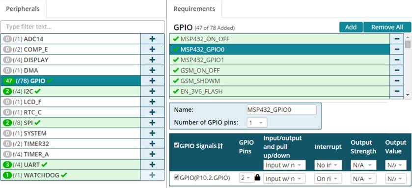
I need interrupt cababilities on P10.1, P10.2, P10.3   .

I m in TQFP package .

now in Pinmux  I can see  interrupt is available , while  in the datasheet  they are reported as "simple"  GPIOs  

please coudl you confirm me   these pins are interrupt capable ?    

TRM is not so clear it seems any P10x is interrupt capable : could you redirect me to proper paper ?

thank you 

best regards

Carlo

  • Hi Colombo,

    Section 4.4 Signal Descriptions of the datasheet (https://www.ti.com/lit/gpn/msp432p4111) lists the specific GPIO ports that have the interrupt capability. It lists only P1-P6 as having interrupt capabilities. This is on pages 24-26. P10 is only listed as "General-purpose digital I/O" and does not look to have interrupt capability. 

    Colombo Carlo said:
    now in Pinmux  I can see  interrupt is available

    Which section of the datasheet or TRM are you referring to here? Can you please elaborate?

    Srinivas

  • HI Srinivas , 

    if you use the PINMUX  utility  you can set  Interrupt on P10x ...

    so  device can only do  interrupt on P1 to P6 ports ?

    thank you 

    regards

    Carlo

  • Hi Carlo,

    The https://www.ti.com/tool/PINMUXTOOL page suggests using SYSCONFIG https://www.ti.com/tool/download/SYSCONFIG. For the MSP432P4111 device, if I enable the interrupt requirement, it does NOT show P10. It only shows P1 - P6. See image below:

    If I specify the interrupt as NONE, then it shows P10. See below.

    Hope that helps.

    Srinivas

  • Hi Srinivas  

    please start for a new project  , I m on Cloud version  , you will be able to enable interrupt on port 10  and genereta proper  code  ( in attach ) 

    GPIOMSP432_P10_1 | GPIO_CFG_IN_NOPULL | GPIO_CFG_IN_INT_FALLING,

        GPIOMSP432_P10_2 | GPIO_CFG_IN_NOPULL | GPIO_CFG_IN_INT_RISING,

        GPIOMSP432_P10_3 | GPIO_CFG_IN_NOPULL | GPIO_CFG_IN_INT_HIGH,

    are you sure  no interrupt capabilities on the device  ?   it is a PINUMUX issue ?   please I need a confirmation here 

    thakn you 

    best regards

    Carlo

    //*****************************************************************************
    // Board.c
    //
    // configure the device pins for different signals
    //
    // Copyright (C) 2015 Texas Instruments Incorporated - http://www.ti.com/ 
    // 
    // 
    //  Redistribution and use in source and binary forms, with or without 
    //  modification, are permitted provided that the following conditions 
    //  are met:
    //
    //    Redistributions of source code must retain the above copyright 
    //    notice, this list of conditions and the following disclaimer.
    //
    //    Redistributions in binary form must reproduce the above copyright
    //    notice, this list of conditions and the following disclaimer in the 
    //    documentation and/or other materials provided with the   
    //    distribution.
    //
    //    Neither the name of Texas Instruments Incorporated nor the names of
    //    its contributors may be used to endorse or promote products derived
    //    from this software without specific prior written permission.
    //
    //  THIS SOFTWARE IS PROVIDED BY THE COPYRIGHT HOLDERS AND CONTRIBUTORS 
    //  "AS IS" AND ANY EXPRESS OR IMPLIED WARRANTIES, INCLUDING, BUT NOT 
    //  LIMITED TO, THE IMPLIED WARRANTIES OF MERCHANTABILITY AND FITNESS FOR
    //  A PARTICULAR PURPOSE ARE DISCLAIMED. IN NO EVENT SHALL THE COPYRIGHT 
    //  OWNER OR CONTRIBUTORS BE LIABLE FOR ANY DIRECT, INDIRECT, INCIDENTAL, 
    //  SPECIAL, EXEMPLARY, OR CONSEQUENTIAL DAMAGES (INCLUDING, BUT NOT 
    //  LIMITED TO, PROCUREMENT OF SUBSTITUTE GOODS OR SERVICES; LOSS OF USE,
    //  DATA, OR PROFITS; OR BUSINESS INTERRUPTION) HOWEVER CAUSED AND ON ANY
    //  THEORY OF LIABILITY, WHETHER IN CONTRACT, STRICT LIABILITY, OR TORT 
    //  (INCLUDING NEGLIGENCE OR OTHERWISE) ARISING IN ANY WAY OUT OF THE USE 
    //  OF THIS SOFTWARE, EVEN IF ADVISED OF THE POSSIBILITY OF SUCH DAMAGE.
    //
    //*****************************************************************************
    
    // This file was automatically generated on 30/9/2020 at 08:56:33
    // by TI PinMux version 4.0.1526 
    //
    //*****************************************************************************
    
    #include <stdbool.h>
    
    #include <ti/drivers/Power.h>
    #include <ti/drivers/power/PowerMSP432.h>
    
    #include <ti/devices/msp432p4xx/inc/msp.h>
    #include <ti/devices/msp432p4xx/driverlib/rom.h>
    #include <ti/devices/msp432p4xx/driverlib/rom_map.h>
    #include <ti/devices/msp432p4xx/driverlib/adc14.h>
    #include <ti/devices/msp432p4xx/driverlib/dma.h>
    #include <ti/devices/msp432p4xx/driverlib/gpio.h>
    #include <ti/devices/msp432p4xx/driverlib/i2c.h>
    #include <ti/devices/msp432p4xx/driverlib/interrupt.h>
    #include <ti/devices/msp432p4xx/driverlib/pmap.h>
    #include <ti/devices/msp432p4xx/driverlib/ref_a.h>
    #include <ti/devices/msp432p4xx/driverlib/spi.h>
    #include <ti/devices/msp432p4xx/driverlib/timer_a.h>
    #include <ti/devices/msp432p4xx/driverlib/timer32.h>
    #include <ti/devices/msp432p4xx/driverlib/uart.h>
    #include <ti/devices/msp432p4xx/driverlib/wdt_a.h>
    
    #include "Board.h"
    
    
    /*
     *  =============================== DMA ===============================
     */
    #include <ti/drivers/dma/UDMAMSP432.h>
    
    #if defined(__TI_COMPILER_VERSION__)
    #pragma DATA_ALIGN(dmaControlTable, 256)
    #elif defined(__IAR_SYSTEMS_ICC__)
    #pragma data_alignment=256
    #elif defined(__GNUC__)
    __attribute__ ((aligned (256)))
    #endif
    static DMA_ControlTable dmaControlTable[8];
    
    /*
     *  ======== dmaErrorHwi ========
     *  This is the handler for the uDMA error interrupt.
     */
    static void dmaErrorHwi(uintptr_t arg)
    {
        int status = MAP_DMA_getErrorStatus();
        MAP_DMA_clearErrorStatus();
    
        /* Suppress unused variable warning */
        (void)status;
    
        while (1);
    }
    
    UDMAMSP432_Object udmaMSP432Object;
    
    const UDMAMSP432_HWAttrs udmaMSP432HWAttrs = {
        .controlBaseAddr = (void *)dmaControlTable,
        .dmaErrorFxn = (UDMAMSP432_ErrorFxn)dmaErrorHwi,
        .intNum = INT_DMA_ERR,
        .intPriority = (~0)
    };
    
    const UDMAMSP432_Config UDMAMSP432_config = {
        .object = &udmaMSP432Object,
        .hwAttrs = &udmaMSP432HWAttrs
    };
    
    
    /*
     *  ======== MSP_EXP432P4111_initGeneral ========
     */
    void MSP_EXP432P4111_initGeneral(void)
    {
        Power_init();
    }
    
    /*
     *  =============================== GPIO ===============================
     */
    #include <ti/drivers/GPIO.h>
    #include <ti/drivers/gpio/GPIOMSP432.h>
    
    /*
     * Array of Pin configurations
     * NOTE: The order of the pin configurations must coincide with what was
     *       defined in MSP_EXP432P4111.h
     * NOTE: Pins not used for interrupts should be placed at the end of the
     *       array.  Callback entries can be omitted from callbacks array to
     *       reduce memory usage.
     */
    GPIO_PinConfig gpioPinConfigs[] = {
        GPIOMSP432_P10_1 | GPIO_CFG_IN_NOPULL | GPIO_CFG_IN_INT_FALLING,
        GPIOMSP432_P10_2 | GPIO_CFG_IN_NOPULL | GPIO_CFG_IN_INT_RISING,
        GPIOMSP432_P10_3 | GPIO_CFG_IN_NOPULL | GPIO_CFG_IN_INT_HIGH,
        GPIOMSP432_P1_0 | GPIO_CFG_IN_NOPULL | GPIO_CFG_IN_INT_NONE,
        GPIOMSP432_P1_1 | GPIO_CFG_IN_NOPULL | GPIO_CFG_IN_INT_NONE,
        GPIOMSP432_P2_4 | GPIO_CFG_IN_NOPULL | GPIO_CFG_IN_INT_NONE,
        GPIOMSP432_P2_6 | GPIO_CFG_IN_NOPULL | GPIO_CFG_IN_INT_NONE,
        GPIOMSP432_P10_4 | GPIO_CFG_IN_NOPULL | GPIO_CFG_IN_INT_NONE,
        GPIOMSP432_P10_5 | GPIO_CFG_IN_NOPULL | GPIO_CFG_IN_INT_NONE,
        GPIOMSP432_P7_4 | GPIO_CFG_IN_NOPULL | GPIO_CFG_IN_INT_NONE,
        GPIOMSP432_P7_5 | GPIO_CFG_IN_NOPULL | GPIO_CFG_IN_INT_NONE,
        GPIOMSP432_P7_6 | GPIO_CFG_IN_NOPULL | GPIO_CFG_IN_INT_NONE,
        GPIOMSP432_P7_7 | GPIO_CFG_IN_NOPULL | GPIO_CFG_IN_INT_NONE,
        GPIOMSP432_P8_0 | GPIO_CFG_IN_NOPULL | GPIO_CFG_IN_INT_NONE,
        GPIOMSP432_P8_1 | GPIO_CFG_IN_NOPULL | GPIO_CFG_IN_INT_NONE,
        GPIOMSP432_P3_0 | GPIO_CFG_IN_NOPULL | GPIO_CFG_IN_INT_NONE,
        GPIOMSP432_P3_1 | GPIO_CFG_IN_NOPULL | GPIO_CFG_IN_INT_NONE,
        GPIOMSP432_P2_7 | GPIO_CFG_IN_NOPULL | GPIO_CFG_IN_INT_NONE,
        GPIOMSP432_P2_5 | GPIO_CFG_IN_NOPULL | GPIO_CFG_IN_INT_NONE,
        GPIOMSP432_P3_4 | GPIO_CFG_IN_NOPULL | GPIO_CFG_IN_INT_NONE,
        GPIOMSP432_P3_5 | GPIO_CFG_IN_NOPULL | GPIO_CFG_IN_INT_NONE,
        GPIOMSP432_P3_6 | GPIO_CFG_IN_NOPULL | GPIO_CFG_IN_INT_NONE,
        GPIOMSP432_P3_7 | GPIO_CFG_IN_NOPULL | GPIO_CFG_IN_INT_NONE,
        GPIOMSP432_P8_2 | GPIO_CFG_IN_NOPULL | GPIO_CFG_IN_INT_NONE,
        GPIOMSP432_P8_3 | GPIO_CFG_IN_NOPULL | GPIO_CFG_IN_INT_NONE,
        GPIOMSP432_P8_4 | GPIO_CFG_IN_NOPULL | GPIO_CFG_IN_INT_NONE,
        GPIOMSP432_P4_1 | GPIO_CFG_IN_NOPULL | GPIO_CFG_IN_INT_NONE,
        GPIOMSP432_P8_5 | GPIO_CFG_IN_NOPULL | GPIO_CFG_IN_INT_NONE,
        GPIOMSP432_P8_6 | GPIO_CFG_IN_NOPULL | GPIO_CFG_IN_INT_NONE,
        GPIOMSP432_P8_7 | GPIO_CFG_IN_NOPULL | GPIO_CFG_IN_INT_NONE,
        GPIOMSP432_P9_0 | GPIO_CFG_IN_NOPULL | GPIO_CFG_IN_INT_NONE,
        GPIOMSP432_P9_1 | GPIO_CFG_IN_NOPULL | GPIO_CFG_IN_INT_NONE,
        GPIOMSP432_P6_0 | GPIO_CFG_IN_NOPULL | GPIO_CFG_IN_INT_NONE,
        GPIOMSP432_P6_1 | GPIO_CFG_IN_NOPULL | GPIO_CFG_IN_INT_NONE,
        GPIOMSP432_P4_0 | GPIO_CFG_IN_NOPULL | GPIO_CFG_IN_INT_NONE,
        GPIOMSP432_P4_4 | GPIO_CFG_IN_NOPULL | GPIO_CFG_IN_INT_NONE,
        GPIOMSP432_P4_2 | GPIO_CFG_IN_NOPULL | GPIO_CFG_IN_INT_NONE,
        GPIOMSP432_P4_3 | GPIO_CFG_IN_NOPULL | GPIO_CFG_IN_INT_NONE,
        GPIOMSP432_P4_7 | GPIO_CFG_IN_NOPULL | GPIO_CFG_IN_INT_NONE,
        GPIOMSP432_P5_0 | GPIO_CFG_IN_NOPULL | GPIO_CFG_IN_INT_NONE,
        GPIOMSP432_P4_5 | GPIO_CFG_IN_NOPULL | GPIO_CFG_IN_INT_NONE,
        GPIOMSP432_P4_6 | GPIO_CFG_IN_NOPULL | GPIO_CFG_IN_INT_NONE,
        GPIOMSP432_P5_1 | GPIO_CFG_IN_NOPULL | GPIO_CFG_IN_INT_NONE,
        GPIOMSP432_P5_2 | GPIO_CFG_IN_NOPULL | GPIO_CFG_IN_INT_NONE,
        GPIOMSP432_P9_5 | GPIO_CFG_IN_NOPULL | GPIO_CFG_IN_INT_NONE,
        GPIOMSP432_P5_3 | GPIO_CFG_IN_NOPULL | GPIO_CFG_IN_INT_NONE,
        GPIOMSP432_P5_4 | GPIO_CFG_IN_NOPULL | GPIO_CFG_IN_INT_NONE,
    };
    
    /*
     * Array of callback function pointers
     * NOTE: The order of the pin configurations must coincide with what was
     *       defined in MSP_EXP432P4111.h
     * NOTE: Pins not used for interrupts can be omitted from callbacks array to
     *       reduce memory usage (if placed at end of gpioPinConfigs array).
     */
    GPIO_CallbackFxn gpioCallbackFunctions[] = {
        NULL,
        NULL
    };
    
    const GPIOMSP432_Config GPIOMSP432_config = {
        .pinConfigs = (GPIO_PinConfig *)gpioPinConfigs,
        .callbacks = (GPIO_CallbackFxn *)gpioCallbackFunctions,
        .numberOfPinConfigs = sizeof(gpioPinConfigs)/sizeof(GPIO_PinConfig),
        .numberOfCallbacks = sizeof(gpioCallbackFunctions)/sizeof(GPIO_CallbackFxn),
        .intPriority = (~0)
    };
    /*
     *  =============================== I2C ===============================
     */
    #include <ti/drivers/I2C.h>
    #include <ti/drivers/i2c/I2CMSP432.h>
    
    I2CMSP432_Object i2cMSP432Objects[Board_I2CCOUNT];
    
    const I2CMSP432_HWAttrsV1 i2cMSP432HWAttrs[Board_I2CCOUNT] = {
        {
            .baseAddr = EUSCI_B1_BASE,
            .intNum = INT_EUSCIB1,
            .intPriority = (~0),
            .clockSource = EUSCI_B_I2C_CLOCKSOURCE_SMCLK,
            .dataPin = I2CMSP432_P6_4_UCB1SDA,
            .clkPin = I2CMSP432_P6_5_UCB1SCL,
        },
        {
            .baseAddr = EUSCI_B3_BASE,
            .intNum = INT_EUSCIB3,
            .intPriority = (~0),
            .clockSource = EUSCI_B_I2C_CLOCKSOURCE_SMCLK,
            .dataPin = I2CMSP432_P6_6_UCB3SDA,
            .clkPin = I2CMSP432_P6_7_UCB3SCL,
        },
    };
    
    const I2C_Config I2C_config[Board_I2CCOUNT] = {
        {
            .fxnTablePtr = &I2CMSP432_fxnTable,
            .object = &i2cMSP432Objects[TEST_TEMP_I2C],
            .hwAttrs = &i2cMSP432HWAttrs[TEST_TEMP_I2C]
        },
        {
            .fxnTablePtr = &I2CMSP432_fxnTable,
            .object = &i2cMSP432Objects[TEST_DISP_I2C],
            .hwAttrs = &i2cMSP432HWAttrs[TEST_DISP_I2C]
        },
    };
    
    const uint_least8_t I2C_count = Board_I2CCOUNT;
    /*
     *  =============================== Power ===============================
     */
    const PowerMSP432_ConfigV1 PowerMSP432_config = {
        .policyInitFxn = &PowerMSP432_initPolicy,
        .policyFxn = &PowerMSP432_sleepPolicy,
        .initialPerfLevel = 2,
        .enablePolicy = true,
        .enablePerf = true,
        .enableParking = true
    };
    
    /*
     *  =============================== SPI ===============================
     */
    #include <ti/drivers/SPI.h>
    #include <ti/drivers/spi/SPIMSP432DMA.h>
    
    /* SPI objects */
    SPIMSP432DMA_Object spiMSP432DMAObjects[Board_SPICOUNT];
    
    /* SPI configuration structure */
    const SPIMSP432DMA_HWAttrsV1 spiMSP432DMAHWAttrs[Board_SPICOUNT] = {
        {
            .baseAddr = EUSCI_B0_BASE,
            .bitOrder = EUSCI_B_SPI_LSB_FIRST,
            .clockSource = EUSCI_B_SPI_CLOCKSOURCE_SMCLK,
            .defaultTxBufValue = 0,
            .dmaIntNum = INT_DMA_INT1,
            .intPriority = (~0),
            .rxDMAChannelIndex = DMA_CH1_EUSCIB0RX0,
            .txDMAChannelIndex = DMA_CH0_EUSCIB0TX0,
            .clkPin = SPIMSP432DMA_P1_5_UCB0CLK,
            .simoPin = SPIMSP432DMA_P1_6_UCB0SIMO,
            .somiPin = SPIMSP432DMA_P1_7_UCB0SOMI,
            .stePin = 0,
            .pinMode = EUSCI_SPI_3PIN
        },
        {
            .baseAddr = EUSCI_A1_BASE,
            .bitOrder = EUSCI_A_SPI_LSB_FIRST,
            .clockSource = EUSCI_A_SPI_CLOCKSOURCE_SMCLK,
            .defaultTxBufValue = 0,
            .dmaIntNum = INT_DMA_INT2,
            .intPriority = (~0),
            .rxDMAChannelIndex = DMA_CH3_EUSCIA1RX,
            .txDMAChannelIndex = DMA_CH2_EUSCIA1TX,
            .clkPin = SPIMSP432DMA_P2_1_UCA1CLK,
            .simoPin = SPIMSP432DMA_P2_3_UCA1SIMO,
            .somiPin = SPIMSP432DMA_P2_2_UCA1SOMI,
            .stePin = 0,
            .pinMode = EUSCI_SPI_3PIN
        },
    };
    
    const SPI_Config SPI_config[Board_SPICOUNT] = {
        {
            .fxnTablePtr = &SPIMSP432DMA_fxnTable,
            .object = &spiMSP432DMAObjects[MSP432_Flash],
            .hwAttrs = &spiMSP432DMAHWAttrs[MSP432_Flash]
        },
        {
            .fxnTablePtr = &SPIMSP432DMA_fxnTable,
            .object = &spiMSP432DMAObjects[TEST_SNS_SPI],
            .hwAttrs = &spiMSP432DMAHWAttrs[TEST_SNS_SPI]
        },
    };
    
    const uint_least8_t SPI_count = Board_SPICOUNT;
    
    /*
     *  =============================== UART ===============================
     */
    #include <ti/drivers/UART.h>
    #include <ti/drivers/uart/UARTMSP432.h>
    
    UARTMSP432_Object uartMSP432Objects[Board_UARTCOUNT];
    unsigned char uartMSP432RingBuffer[Board_UARTCOUNT][32];
    
    /*
     * The baudrate dividers were determined by using the MSP432 baudrate
     * calculator
     * http://software-dl.ti.com/msp430/msp430_public_sw/mcu/msp430/MSP430BaudRateConverter/index.html
     */
    const UARTMSP432_BaudrateConfig uartMSP432Baudrates[] = {
        /* {baudrate, input clock, prescalar, UCBRFx, UCBRSx, oversampling} */
        {
            .outputBaudrate = 115200,
            .inputClockFreq = 12000000,
            .prescalar = 6,
            .hwRegUCBRFx = 8,
            .hwRegUCBRSx = 32,
            .oversampling = 1
        },
        {115200, 6000000,   3,  4,   2, 1},
        {115200, 3000000,   1, 10,   0, 1},
        {9600,   12000000, 78,  2,   0, 1},
        {9600,   6000000,  39,  1,   0, 1},
        {9600,   3000000,  19,  8,  85, 1},
        {9600,   32768,     3,  0, 146, 0}
    };
    
    const UARTMSP432_HWAttrsV1 uartMSP432HWAttrs[Board_UARTCOUNT] = {
        {
            .baseAddr = EUSCI_A3_BASE,
            .intNum = INT_EUSCIA3,
            .intPriority = (~0),
            .clockSource = EUSCI_A_UART_CLOCKSOURCE_SMCLK,
            .bitOrder = EUSCI_A_UART_LSB_FIRST,
            .numBaudrateEntries = sizeof(uartMSP432Baudrates) /
                sizeof(UARTMSP432_BaudrateConfig),
            .baudrateLUT = uartMSP432Baudrates,
            .ringBufPtr  = uartMSP432RingBuffer[MSP432_UART],
            .ringBufSize = sizeof(uartMSP432RingBuffer[MSP432_UART]),
            .rxPin = UARTMSP432_P9_6_UCA3RXD,
            .txPin = UARTMSP432_P9_7_UCA3TXD,
        },
        {
            .baseAddr = EUSCI_A0_BASE,
            .intNum = INT_EUSCIA0,
            .intPriority = (~0),
            .clockSource = EUSCI_A_UART_CLOCKSOURCE_SMCLK,
            .bitOrder = EUSCI_A_UART_LSB_FIRST,
            .numBaudrateEntries = sizeof(uartMSP432Baudrates) /
                sizeof(UARTMSP432_BaudrateConfig),
            .baudrateLUT = uartMSP432Baudrates,
            .ringBufPtr  = uartMSP432RingBuffer[GSM_UART],
            .ringBufSize = sizeof(uartMSP432RingBuffer[GSM_UART]),
            .rxPin = UARTMSP432_P1_2_UCA0RXD,
            .txPin = UARTMSP432_P1_3_UCA0TXD,
        },
        {
            .baseAddr = EUSCI_A2_BASE,
            .intNum = INT_EUSCIA2,
            .intPriority = (~0),
            .clockSource = EUSCI_A_UART_CLOCKSOURCE_SMCLK,
            .bitOrder = EUSCI_A_UART_LSB_FIRST,
            .numBaudrateEntries = sizeof(uartMSP432Baudrates) /
                sizeof(UARTMSP432_BaudrateConfig),
            .baudrateLUT = uartMSP432Baudrates,
            .ringBufPtr  = uartMSP432RingBuffer[IR_UART],
            .ringBufSize = sizeof(uartMSP432RingBuffer[IR_UART]),
            .rxPin = UARTMSP432_P3_2_UCA2RXD,
            .txPin = UARTMSP432_P3_3_UCA2TXD,
        },
    };
    
    const UART_Config UART_config[Board_UARTCOUNT] = {
        {
            .fxnTablePtr = &UARTMSP432_fxnTable,
            .object = &uartMSP432Objects[MSP432_UART],
            .hwAttrs = &uartMSP432HWAttrs[MSP432_UART]
        },
        {
            .fxnTablePtr = &UARTMSP432_fxnTable,
            .object = &uartMSP432Objects[GSM_UART],
            .hwAttrs = &uartMSP432HWAttrs[GSM_UART]
        },
        {
            .fxnTablePtr = &UARTMSP432_fxnTable,
            .object = &uartMSP432Objects[IR_UART],
            .hwAttrs = &uartMSP432HWAttrs[IR_UART]
        },
    };
    
    const uint_least8_t UART_count = Board_UARTCOUNT;
        
    /*
     *  =============================== Watchdog ===============================
     */
    #include <ti/drivers/Watchdog.h>
    #include <ti/drivers/watchdog/WatchdogMSP432.h>
    
    WatchdogMSP432_Object watchdogMSP432Objects[Board_WATCHDOGCOUNT];
    
    const WatchdogMSP432_HWAttrs watchdogMSP432HWAttrs[Board_WATCHDOGCOUNT] = {
        {
            .baseAddr = WDT_A_BASE,
            .intNum = INT_WDT_A,
            .intPriority = (~0),
            .clockSource = WDT_A_CLOCKSOURCE_SMCLK,
            .clockDivider = WDT_A_CLOCKDIVIDER_8192K
        },
    };
    
    const Watchdog_Config Watchdog_config[Board_WATCHDOGCOUNT] = {
        {
            .fxnTablePtr = &WatchdogMSP432_fxnTable,
            .object = &watchdogMSP432Objects[MyWATCHDOG1],
            .hwAttrs = &watchdogMSP432HWAttrs[MyWATCHDOG1]
        },
    };
    
    const uint_least8_t Watchdog_count = Board_WATCHDOGCOUNT;
    
    1768.Board.h

  • Hi Carlo,

    Colombo Carlo said:
    are you sure  no interrupt capabilities on the device  ?

    The datasheet section 4.4, Table 4-3. Signal Descriptions clearly states that the interrupts are only available on ports P1 - P6. We will have to go with that.

    Colombo Carlo said:
    it is a PINUMUX issue ?

    The downloadable https://www.ti.com/tool/SYSCONFIG which is a release in September 2020 also clearly shows only P1-P6 if interrupt is required, as I mentioned in.my earlier post https://e2e.ti.com/support/microcontrollers/msp430/f/166/p/945095/3492031#3492031

    The problem could be with the PINMUX tool on the cloud which was a January 2020 release. There must be a bug in it. 

    Srinivas

**Attention** This is a public forum