This thread has been locked.

If you have a related question, please click the "Ask a related question" button in the top right corner. The newly created question will be automatically linked to this question.

MSP430I2041: Thermocouple Ground Loop Issue

Part Number: MSP430I2041
Other Parts Discussed in Thread: MSP430F6721,

Hello,

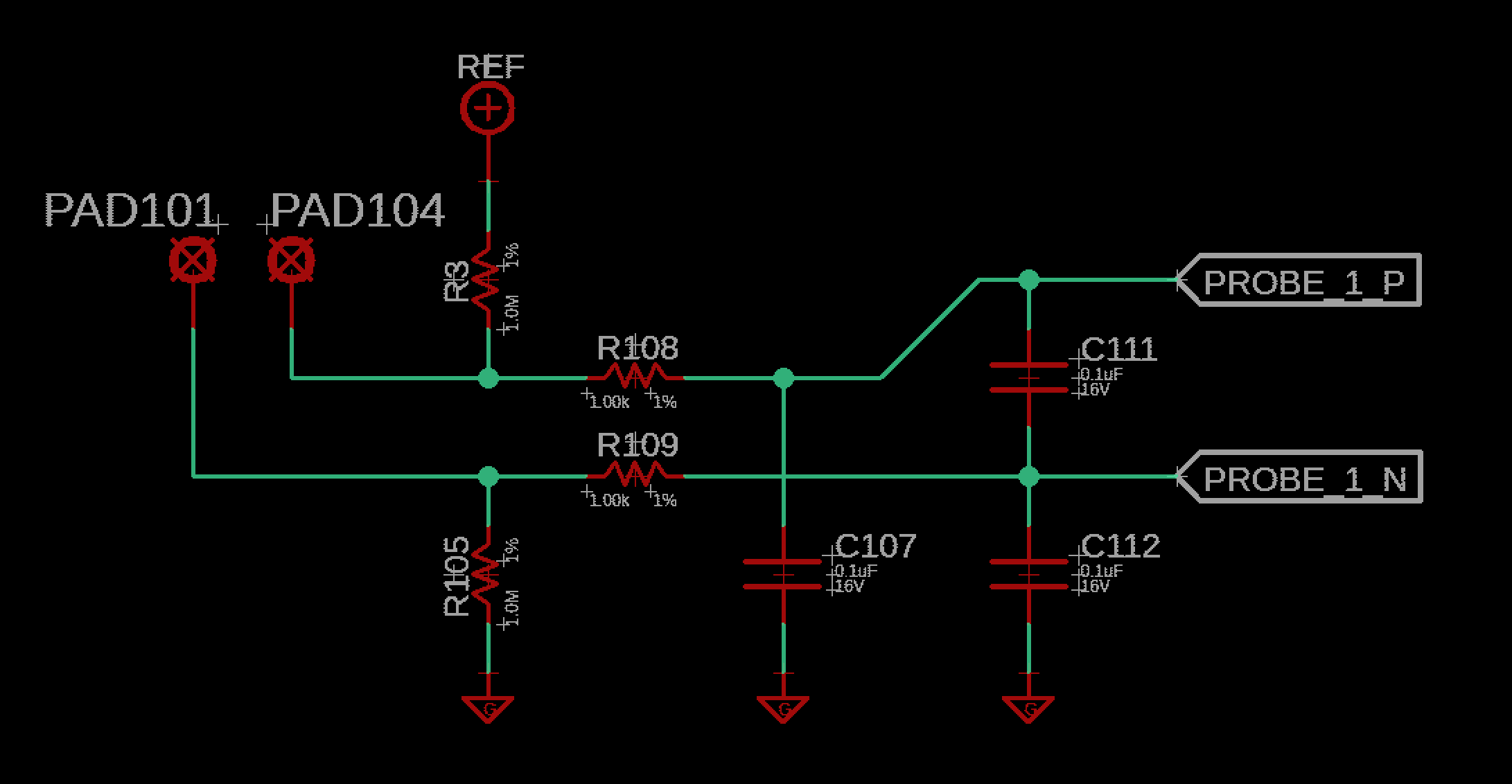
I'm currently working on a design that will be used to sense a K-Type thermocouple. I have two identical designs except with the processor being different, a MSP430I2041 vs a MSP430F6721.  Even though the input filtering is the exact same, I see each board behaving differently during operation. 

I'm seeing issues specifically when a grounded thermocouple sheath makes contact with another "ground" while the unit is plugged in to USB and a Wall Charger. The reading on the MSP430I starts to read very inaccurate numbers, but the MSP430seems to read the TC values appropriately. 

Like I mentioned the designs are the same except for the MSPs, I noticed that the MSP430F's SD24 has about 50dB better rejection ration than the MSP430I. Could this along with the SD24 just being better in general on the F version be why the it is reading the values correctly?

Any thoughts or suggestions would be greatly appreciated!

Thanks!

  • Hi Tyler,

    Thanks for your detailed post.

    Tyler FB said:
    I'm seeing issues specifically when a grounded thermocouple sheath makes contact with another "ground" while the unit is plugged in to USB and a Wall Charger. The reading on the MSP430I starts to read very inaccurate numbers, but the MSP430seems to read the TC values appropriately. 

    If you could elaborate more, I think it'd be helpful. A generic diagram showing the normal connections and then shorted connections would help. I'm assuming that the +/- ADC inputs are connected to the +/- wires of the thermocouple, but you could be connecting the negative ADC inputs to ground in a single-ended input configuration.

    I have seen issues when all the negative ADC inputs are connected together. For sake of discussion, let's assume there are three unique signals connected to the positive ADC inputs. If one of those signals on the positive inputs gets turned off or gets disconnected, the results for all the other channels will be skewed because the offset voltage changes for all channels due to 2/3 (versus 3/3) the current flowing through the negative inputs. I don't think this is happening in your case, but I still wanted to share it.

    Tyler FB said:
    Like I mentioned the designs are the same except for the MSPs, I noticed that the MSP430F's SD24 has about 50dB better rejection ration than the MSP430I. Could this along with the SD24 just being better in general on the F version be why the it is reading the values correctly?

    The rejection ratio is a good observation, and it could be the explanation for this behavior. If the shorting scenario described above applies the same common-mode signal to the +/- ADC inputs, then this would explain the difference in performance.

    Regards,

    James

  • Hi James,

    Thanks for the response! To elaborate a little more, I am using the ADC in differential mode and only have the N tied to ground through a resistor in the order of megaohms (between 1MEG and 20MEG, still trying to optimized my response). Below is a generic schematic of the design. PROBE_1_P goes to the P of the MSP SD24, and PROBE_1_N goes to the N of the MSP SD24. PAD104 is going to the P of the thermocouple and PAD105 is going to the N of the thermocouple.

    The situation of when the circuit starts acting weird is when PAD101 is getting connected to an external ground through the sheath of the grounded thermocouple and the circuit is powered through USB. When using an unground thermocouple, this problem goes away. So the N terminal of the circuit is getting a secondary ground connection. I have also tried making it truly differential by removing the filtering circuit and connecting the thermocouple directly to the ADC inputs. This produced the same results as with the filter.

    I was able to turn the ADC reading into a "simplistic o'scope" and figured out that it was 60 Hz AC "noise". So my thoughts are that it truly is that the SD24_B in the version is just much better than the SD24 in the I version. Any thoughts?

    Do you happen to know if there are other MSPs with the SD24_B that are in a smaller package, maybe a QFN? The package of the F device is huge compared to the I. 

    Thank you!

  • Hi Tyler,

    Thanks again for the extensive details. It's very helpful!

    Tyler FB said:
    The situation of when the circuit starts acting weird is when PAD101 is getting connected to an external ground through the sheath of the grounded thermocouple and the circuit is powered through USB. When using an unground thermocouple, this problem goes away. So the N terminal of the circuit is getting a secondary ground connection. I have also tried making it truly differential by removing the filtering circuit and connecting the thermocouple directly to the ADC inputs. This produced the same results as with the filter.

    If I understand your circuit correctly, REF provides a DC bias to both ADC inputs. This would be the common-mode input whereas the thermocouple output voltage is the differential input. When the external ground is connected to the thermocouple, the common-mode voltage level changes but also gets much noisier than the clean REF source, probably due to the power supply switching. Then, because the CMRR performance of the i20xx SD24 module is lower than the CMRR performance of the F67xxA SD24_B module, the noise is more noticeable on the i20xx-based design.

    Is there any way you can prevent this accidental shorting in your design? If so, then I'd use the i20xx. If not, then I would recommend using the F67xxA device.

    Tyler FB said:
    I was able to turn the ADC reading into a "simplistic o'scope" and figured out that it was 60 Hz AC "noise". So my thoughts are that it truly is that the SD24_B in the version is just much better than the SD24 in the I version. Any thoughts?

    The difference in CMRR performance is definitely noticeable in this scenario. I would consider the SD24_B module to be better than SD24 (e.g. resolution, CMRR, more flexible PGA settings, more flexible modulation frequencies, etc.), but the SD24 has a continuous-time architecture which is less stringent on the minimum settling time of the external circuitry. Basically, this means that higher impedance circuits can be used with SD24 than SD24_B. To learn more about these differences, I'd recommend reading through the Answers to Common Sigma-Delta ADC Questions on MSP MCUs app note that I wrote recently.

    The PSRR performance is roughly the same between these two modules, so that wouldn't explain this behavior.

    In your initial post, you already suspected that the CMRR difference was the cause, so I can't say I've added much here but hopefully our discussion has helped.

    Regards,

    James

  • Tyler FB said:
    Do you happen to know if there are other MSPs with the SD24_B that are in a smaller package, maybe a QFN? The package of the F device is huge compared to the I. 

    Unfortunately, the smallest package for the SD24_B devices is a 80-pin LQFP package. Thinking about this made me remember the MSP430AFE25x devices which feature the SD24_A module (also compared in SLAA957). Its CMRR performance is better than i20xx (90dB versus 60dB), so you may want to consider this device as an alternative. They have less memory and support inputs with smaller max amplitudes than the i20xx devices, but I wanted to mention them. They are offered in a 24-pin TSSOP (PW) package.

    Regards,

    James

**Attention** This is a public forum