This thread has been locked.

If you have a related question, please click the "Ask a related question" button in the top right corner. The newly created question will be automatically linked to this question.

LP-MSP430FR2476: MSP430FR2476 Temperature Sensor Calibration Coefficients are incorrect.

Part Number: LP-MSP430FR2476
Other Parts Discussed in Thread: MSP430FR2476, MSP430FR5969

I'm using an LP-MSP430FR2476 evaluation board. When trying to use the calibration coefficients for the internal temperature sensor I'm seeing two issues.

1. The example code MSP430FR267x_ADC12_16 uses 85C for this calculation, while the data sheet specifies 105C. This is addressed in the linked ticket.

2. The coefficients stored in the part appear to be incorrect.
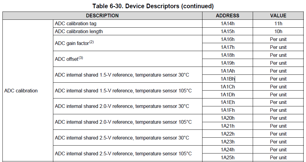
The datasheet specifies the follow locations for the temperature sensor. 

Using these addresses and doing a memory dump produces:
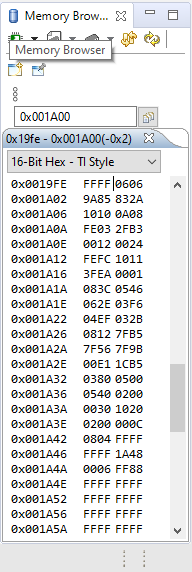
Description Address 16bit
ADC internal shared 1.5-V reference, temperature sensor 30°C 1A1Ah 083Ch
ADC internal shared 1.5-V reference, temperature sensor 105°C 1A1Ch 0546h
ADC internal shared 2.0-V reference, temperature sensor 30°C 1A1Eh 062Eh
ADC internal shared 2.0-V reference, temperature sensor 105°C 1A20h 03F6h
ADC internal shared 2.5-V reference, temperature sensor 30°C 1A22h 04EFh
ADC internal shared 2.5-V reference, temperature sensor 105°C 1A24h 032Bh

The way the equation uses these calibration values is as y coordinates on the slope of the transfer function for the temperature sensor. This would mean the slope of the function is negative, but the ADC reading increases when temperature rises. What am I missing here? These values appear to be wrong, or the example code is using them incorrectly.

  • Hi Hunter,

    1) It appears that this bug was reported previously since the MSP430FR2476 can support up to 105C internally and the code was just transposed across multiple devices with different maximum temperatures. I will check with the team to see the status of updating the code. https://e2e.ti.com/support/microcontrollers/msp430/f/166/t/931441?MSP430FR2476-MSP430FR267x-Demo-ADC-Sample-A12-Temp-and-Convert-to-oC-and-oF

    2) For the ADC calibration coefficients stored in the Memory Browser, the data is stored in little endian (LSB first), so if you look at the data in 8-bit Hex - TI Style, it should make more sense. 

    In terms of your last question, could you clarify with an example by what you mean "the equation uses these calibration values is as y coordinates on the slope of the transfer function for the temperature sensor" and "the slope of the function is negative"? Although the code is using an 85C calibration value, the equation implemented in line 142 of the code example matches the equation in section 1.13.3.3 of the User's Guide.

  • I'm basically rewording the section 1.13.3.3 as I understand it. If i'm reading it correctly, the TLV values are stored in mV and are stored as the measured voltage at two temperatures, those two points are 30C and 105C. 

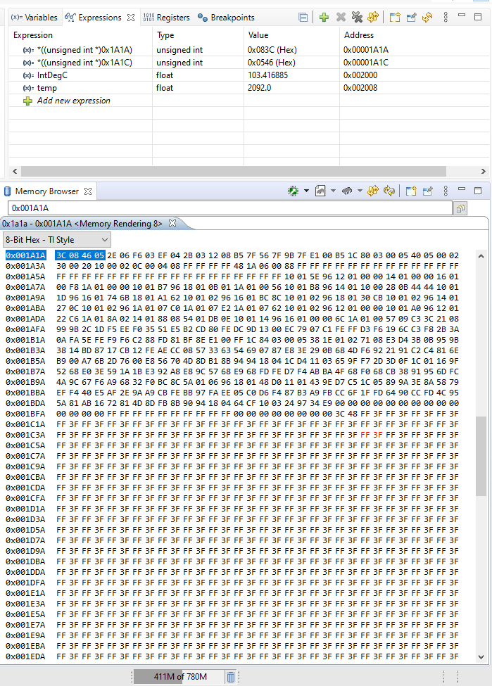
    When I read the memory for 1.5V Reference i get the data below. If we use all decimal in the give equation, do you agree that 2108 and 1350 are the correct values based on the endianness and memory locations?

    ADC internal shared 1.5-V reference, temperature sensor 30°C 1A1Ah 083Ch 2108 decimal
    ADC internal shared 1.5-V reference, temperature sensor 105°C 1A1Ch 0546h 1350 decimal

    This indicates that the calibration value was lower (less mV) at 105C than it was at 30C. This is what doesn't make since. When I heat up the part, the ADCMEM0 value goes UP. So one would expect the 105C calibration value to be bigger than the 30C calibration value.

    The same document indicates in section 21.2.7.8 that the expected transfer function has a positive slope. Where the 105C reading is higher than the 30C reading. Unless I'm interpreting the calibration data wrong, the 105C value is less than the 30C value, which is wrong.

    With the example code the equation returns approximately 30C no matter whether the part is heated up or cooled down.

    If you plot the equation using CALADC_15V_30C = 2108 and CALADC_15V_105C = 1350. You get a negative slope.

    Is this macro somehow not reading the memory as expected? Seems that it matched the Memory Browser and the Expression Window.

    #define CALADC_15V_30C *((unsigned int *)0x1A22) // Temperature Sensor Calibration-30 C

  • Hi Hunter,

    Apologize for the slight delay, I was consulting with the team in regards to how the internal temperature sensor works and what the expected behavior for the behavior should be in regards to internal die temperature and ADC memory value. 

    It is expected for the ADC value to be related to the change in temperature, therefore, you will see the ADC value increase if the temperature increases

    According to the User's Guide, the equation in Section 1.13.3.3:

    V_sense = TC_sensor * Temp + V_sensor is what calculates V_sense, the sense voltage that gets converted into an ADC value based upon the 1.5-V reference voltage. The slope of the equation, TC_sensor, is positive, which explains the positive slope between ADC value and temperature. 

    In regards to the temperature equations we have been referencing, the ADC calibration values at 30C and 105C are just correction offsets, meaning that the offset values are linearly interpolated because offset values inside of the MCU ADCs varies greatly with temperature. These equations calculate what the internal temperature should be based on the offsets of the room and high temperature. 

    In regards to seeing temperatures at around 30 degrees no matter how much the part is cooled down or heated up, could you provide some test points / screenshots of the Expressions window at a high temp and cold temp? For instance, I see temp = 2092.0 and IntDegC = 103.41 in the screenshot, what temperature was this test with?

  • Hi Aaron,

    Thanks for the help. These are the captured values. Can you demonstrate the calculation?

    Calibration Values: 30C = 2108, 105C = 1350. All values in decimal

    Ambient Temp ADCMEM0 Reading(1.5 vRef, 12Bit)
    30C 2115
    45C 2220
    70C 2398

  • I don't have this part but I checked on a FR5969 Launchpad and found calibration values of: $1a1a - 2721 and $1a1c - 3184. This is consistent with the ADC count increasing with increasing temperature.

    From the guide the correction would be: (ADC(raw) - 2721) * ((85-30)/3184-2721)) + 30

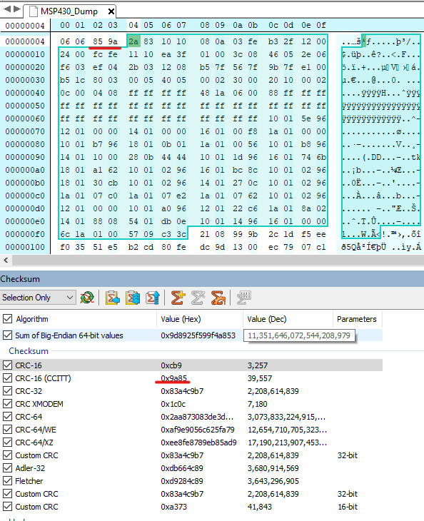
    There appears to be a problem with your correction data. Have you checked the CRC for the TLV data to verify it is correct?

  • David,

    Agreed. Your calculation and example confirms how I expect the calibration values to be interpreted and the equation to work. So it does seems like my calibration data is wrong on this unit.

    I believe however my data set passes CRC check.

  • Hi Hunter,

    I believe we have come up with an explanation of the issue and a temporary solution:

    Issue - ADC high temp calibration value in MSP430FR2476 is half of the calibration value it should be at (in your case, 2700 instead of 1350).

    Temp Solution - Multiply CALADC_15V_85C value by 2 or shift to the left by 1 bit.

    After David's post showing that the ADC calibration value for high temp was higher than the room temp value in MSP430FR5969 (positive slope), I tried the ADC temperature sensor code example for a few LaunchPads (FR5969, FR2433) and they had a larger high temp calibration value than the room temp calibration value (as it is supposed to be). On my MSP430FR2476 LaunchPad, I had very similar values to yours (~2100 for 30C and ~1350 for 85C).

    Looking through your data, the 30C calibration value seemed fine because 30C yielded ADCMEM0 = 2115, which is close to the calibration value. So the 105C temp calibration value seemed off. I did a backwards solve for that calibration value based on (45C, 2220) and got a high temp calibration value of 2668, which is close to twice the value of 1350 for CALADC_15V_85C.

    Here is the equation: 45 = [ ((2220 - 2108) * (105 - 30)) / (x - 2108) ] + 30          //solve for x 

    We will discuss internally how to deal with future concerns. Thank you for providing data and David as well for sharing the discovery in the MSP430FR5969 LaunchPad. Let us know if you have any more questions about this. 

  • Thanks Aaron and team for the help and confirmation of the issue. It is much appreciated!


    I will add we have just gotten a few of our prototype boards with MSP430FR2476TRHB populated on them. The first few I have spot checked are not showing this issue. So I don't know if it only affects a specific manufacturing run, or only launchpads or its just random.

  • It's not unusual for (early) Launchpads to be populated with pre-production "X" devices ("XMS", or "XFR" in this case), and for "X" devices to have a few quirks around the edges.

  • Hi Hunter, 

    What is the lot code number of your device? Please see section 5 of the Erratasheet to find the lot number on the MSP430FR2476 device. 

  • Hi Aaron,

    The die markings are:

    XFR2476

    8CTG4

    AHHY A

    The Launchpad serial number is: 27W1911000773

**Attention** This is a public forum