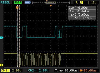
Here are some setup functions I've used to initialize my system:
void accel_init() {

	//PIN CONFIGURATION for I2C on P4.0 and 4.1. Note 4.0 is SDA, 4.1 is SCL
	P4SEL1 |= (SDA | SCL);
	P4SEL0 &= ~(SDA | SCL);

	UCB1CTLW0 |= UCSWRST;//This command enables setup of the UCB.
	UCB1CTLW0 |= UCMODE_3 | UCMST | UCSYNC | UCSSEL_2;//I2C mode | master | synchronous | SMCLCK
	UCB1CTLW0 &= ~UCTR;//receiving data mode
	UCB1CTLW1 |= UCASTP_2;//stop condition generated automatically
	UCB1BRW = 3;//set baud rate, 10^6/3=333.333k
	UCB1BR1 = 0;

	UCB1TBCNT = 1;//send one byte at a time to slave
	UCB1I2CSA = 0x26;//address of slave.

	UCB1CTLW0 &= ~UCSWRST;//disable setup of the UCB.

	//Interrupts:
	UCB1IE |= UCRXIE | UCNACKIE | UCBCNTIE | UCSTPIE;//currently receive interrupt | nack interrupt | cnt value reached interrupt | start interrupt

}

void initMSP430(void) {

    /*********************** Test Data Generator 1 kHz *********************/
	P9DIR   |= BIT1 | BIT2 | BIT3 | BIT4;   // Test Data Output
	TA2CTL   = TASSEL__SMCLK | MC__CONTINUOUS | TACLR;
	TA2CCR1  = 1000;                                    // 1MHz * 1/1000 Hz
	TA2CCTL1 = CCIE;                                    // enable interrupts
	testcnt  = 0;                                       // start test counter at 0

    /**************************** PWM Backlight ****************************/

	P1DIR   |= BIT3;
	P1SEL0  |= BIT3;
	P1SEL1  &= ~BIT3;
	TA1CCR0  = 511;
	TA1CCTL2 = OUTMOD_7;
	TA1CCR2  = 255;
	TA1CTL   = TASSEL__ACLK | MC__UP | TACLR;

    /******************************** SPI **********************************/

	P2DIR  |=   LCD_CS_PIN;	                    // DC and CS
	P4DIR  |=   LCD_DC_PIN;
	P1SEL0 |=   LCD_MOSI_PIN | LCD_UCBCLK_PIN;      // MOSI and UCBOCLK
	P1SEL1 &= ~(LCD_MOSI_PIN | LCD_UCBCLK_PIN);

	UCB0CTLW0 |= UCSWRST;		// Reset UCB0

    /*
     * UCBxCTLW0 	 - eUSCI_Bx Control Register 0
     * UCSSEL__SMCLK - SMCLK in master mode
     * UCCKPL 		 - Clock polarity select
     * UCMSB		 - MSB first select
     * UCMST		 - Master mode select
     * UCMODE_0      - eUSCI mode 3-pin SPI select
     * UCSYNC		 -	Synchronous mode enable
     */
    //UCB0CTLW0 |= UCSSEL__SMCLK | UCCKPL | UCMSB | UCMST | UCMODE_0 | UCSYNC;
	UCB0CTLW0 |= UCSSEL__SMCLK | UCCKPH | UCMSB | UCMST | UCMODE_0 | UCSYNC;
    //    UCB0CTLW0 = UCCKPH + UCMSB + UCMST + UCSYNC + UCSSEL_2; // 3-pin, 8-bit SPI master


	UCB0BR0   |= 0x01;         // Clock = SMCLK/1
	UCB0BR1    = 0;
	UCB0CTL1  &= ~UCSWRST;     // Clear UCSWRST to release the eUSCI for operation
	PM5CTL0   &= ~LOCKLPM5;    // Unlock ports from power manager

	__enable_interrupt();

}
And here is my main function:
void main(void) {
    WDTCTL = WDTPW | WDTHOLD;	// kill the watchdog

    initMSP430();
    accel_init();

    __delay_cycles(10);

	/*The goal now is to send the desired information when the interrupts are enabled
	 * I will try to do this using the cnt interrupt system*/
    	UCB1CTLW0 |= UCTR | UCTXSTT;//start transmitting
    	UCB1TXBUF = 0x01;//send 1


    while (TRUE) {
    	P6DIR ^= BIT1;//just whatever. _nop() would probably be fine here too.
    }
}
I simply want the UCBCNTIFG to trigger. In debug mode, the flag is never thrown. I do not understand why. According to the Family User Guide (pg. 841 of the April 2020 revision) this interrupt is available in master mode. It should occur after transmitting one byte because I've set UCB1TBCNT = 1 and because automatic stop conditions are being generated per UCB1CTLW1 |= UCASTP_2. The interrupt is enabled is the accel_init() function, and __enable_interrupt() is called in the initMSP430() function, so GIE should be set. I have the system set to transmitting mode and call the start condition in main(). The buffer could contain whatever, but happens to be 0x01.
Since I am sending a byte, and UCB1 is tied to the smclk, my expectation is that it will take somewhere around 8 clock cycles for it to send a byte. Thus, the interrupt flag should throw around that time, and it should fall into my ISR (which is an infinite while loop where I've stuck a breakpoint in the debugger). However, it does not. The interrupt is not triggering at all, and I don't understand why. Instead, the program falls into the main() while() loop that just toggles an unused pin direction.
Can anyone shed some light on this? With my device, I can't get any interrupt flags to throw when attempting I2C communications, and I'm worried I've done something improper in the setup. I can't rule out a hardware issue, but if the flag should throw here, and there's nothing wrong with the software, then that would suggest a hardware problem.
Any help would be greatly appreciated.


