This thread has been locked.

If you have a related question, please click the "Ask a related question" button in the top right corner. The newly created question will be automatically linked to this question.

CCS/MSP430FR2433: Can't program the micro on my custom board with the launchpad

Part Number: MSP430FR2433
Other Parts Discussed in Thread: TPS560430

Tool/software: Code Composer Studio

Hello 

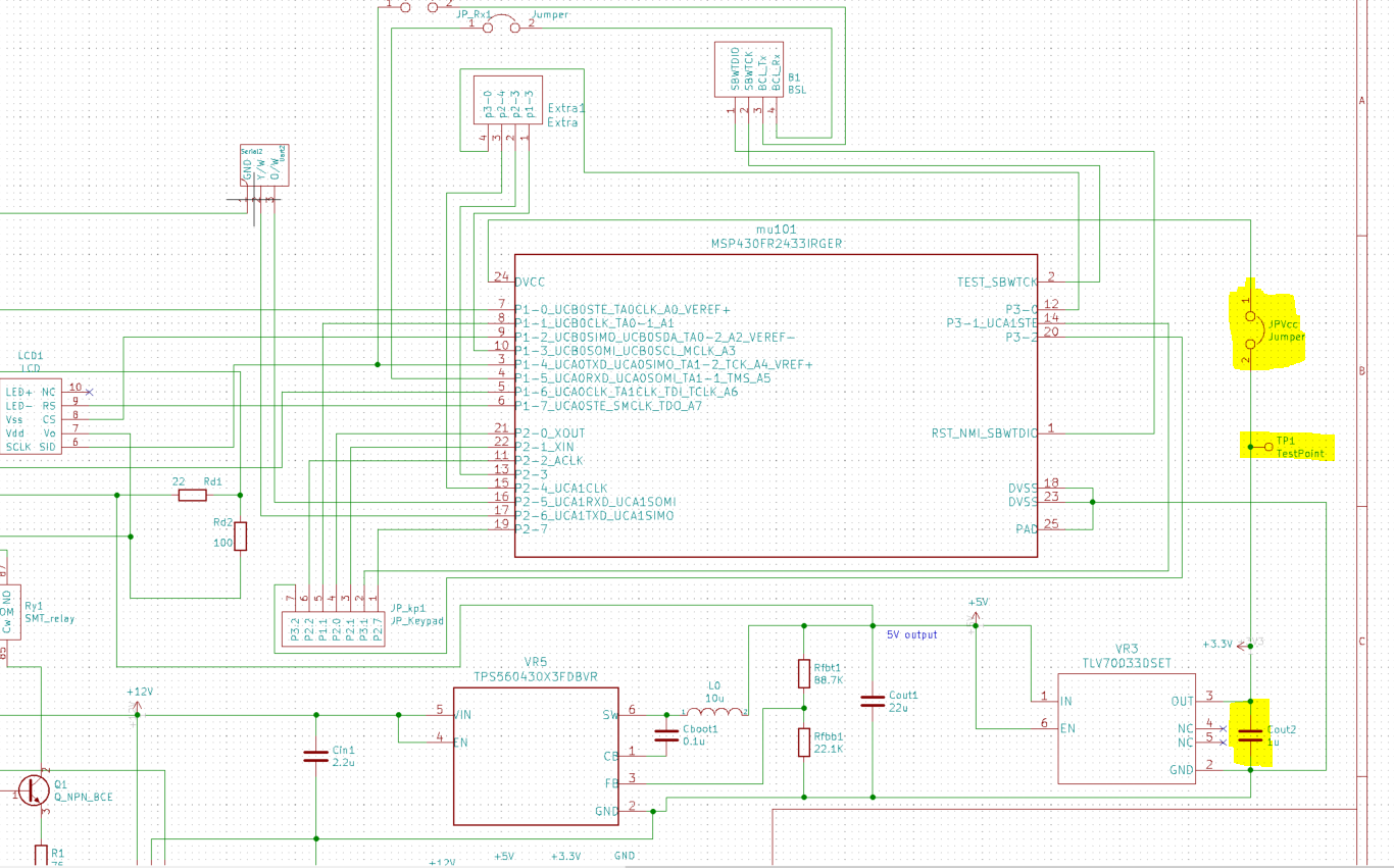
I wrote firmware for a certain project of mine using the Launchpad of msp430fr2433. Now I want to design a custom board that just has the micro and can be programmed using the launchpad. 

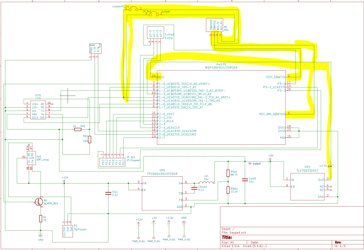
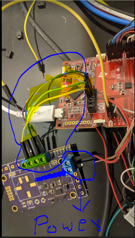
I designed the board and made manual connections with the required pins and connected them to the J101 on the launchpad. I have attached the screenshot of the schematic to this message. When I try to program it, CCS say's "Error connecting to the target: Unknown device". I checked and see that the micro PIN 24 is getting 2.8V. The UART TX line P1.4 is at 3.3V. Seems like the micro is getting the power. Not sure why it's not able to communicate. 

I connected SDWTCK, SBWTDIO, P1.4, P1.5, 5V, and Gnd. I also pulled SBWTDIO high with a 47K resistor (Not on the schematic). Still no luck. What did I do wrong? Did I miss something? 

From my understanding, Launchpad uses BISPI to program the micro. I just have to connect SDWTCK, SBWTDIO for this to work. But got the same error. 

  • I'm wondering why you're getting 2.8V out of the TLV70033. Are you fairly certain your 5V rail is really +5V?

    Is there a way to power the 3V3 on your board directly from the Launchpad? That would allow you to see if the power supply is getting in the way somehow.

    [Edit: Also, I don't see a bypass cap between Vcc and GND. Some MSP430 devices are pickier about this than others, but I have encountered some that wouldn't program if I didn't put one in. ]

    [Edit: I was wrong about the screw terminals since that's the 12V rail.]]

  • Yes. I checked the voltage at the output of the 5V regulator and the input of the TLV70033. It is solid 5V. No problem here. I measured voltage at pin 24 of the micro, I got 2.8V. But the UART TX line has 3.3V. Not sure how?

    No. The board is power by connecting to a 2 pin connected. You need at least 5V there since it's connected to a 5V switching regulator. I don't have access to the power pin of the micro. Can't give it 3.3V directly.  The datasheet says it needs a minimum of 1.8V. We are well above the minimum right?  

    Actually, it will be quite hard. The micro that I have has pads underneath. I can't access the Vcc pad to solder a cap. Same story with TLV70033. I'll try but I might ruin the board for good. 

    A friend of mine told me to reduce the speed of JTAG. Apparently, his team did that when they faced the same problem. I'll try this before I try to solder a cap. Do you have any other suggestions before I try to solder the cap? Please let me know. 

    Thank you 

    Varun R

  • The MCU will run down to 1.8V (it needs 2V to start up). But the programmer is running at 3,3V, and may be objecting to not seeing 3.3V on the SBW pins. More generally I'm just concerned why the regulator isn't working properly.

    If adding a cap is too chancy, try slowing down the JTAG first. As I recall there's also an option nearby for setting the target voltage; I'm not sure this works on a Launchpad, but you can try it. If it works, this wouldn't adjust the actual Vcc, but would tell the programmer to look for a different voltage.

    The TXD=3.3V is a bit odd. It looks like it is also connected to LC01(?), which is powered from +5V. I suggest you disconnect the RXD/TXD wires for now; they aren't necessary for SBW programming.

  • Hello Bruce, 

    I have changed the target voltage to 2.6V and reduced the speed to "Slow" I have attached screenshots of the changes as well just to get a second opinion. Still no luck.

    I do see that the voltage on the TDIO line reduced to 2.6 from 3.2 before. The clock is reading 3.2V when I try to load the program. But still, no target device found. 

    I connected a 100uF cap between TDIO and GND as well. I can't put a cap at VCC of the micro. I disconnected the UART line from the launchpad and but I'm still measuring the fluctuating voltage on the UART TX line. The micro doesn't seem to be dead but can't be found by the bootloader. 

    Is there anything else that I can do with this board? Else I will have a design a new board. This time I''ll make provisions to power the micro from straight 3.3V too and will have test points to check the voltages. This is a last-ditch option. It would be ideal if I figured out the problem on this board. It will save me time and money. 

    Varun R

  • I suspected that the Launchpad (eZ-FET) didn't deal with anything other than 3.3V, and I think you've just demonstrated it. (But it was worth a try.)

    From the photo, it appears you're supplying 5V to the "12/24V" input. What happens if you put, say, 12V there?

  • Well, I'm glad I was able to do that. In order for me to salvage this board, I need to figure out why the voltage regulator is given 2.7V instead of 3.3V. I checked and it's getting 5V input. I used this regulator because this is the exact regulator launch pad used. Not sure why it's giving 2.7V. I'm looking into this now. 

    Nothing happens. the 12V goes to the regulator (Normal operational voltage), so it gives out 5V again which goes to the 3.3V regulator which goes to the micro. No matter 5V or 12V the micro should get 3.3V. But it's only getting 2.7V. 

    I think I need to change the regulator. This is not a fixed regulator as mentioned on Digikey. This is connected to another DC-DC convertor on the launchpad which is not the case on my custom board. I have attached a screenshot of this here. 

    To test out this theory, I'll unsolder the regulator, try to solder a wire to the output pad of this regulator, and connect it directly to 3.3V on the launchpad. This will ruin the board but at least it will confirm if it's the regulator. In the next board, I'll for sure know the problems that I have to fix for this to work. This board would not have been a total waste of time. 

    Unless you have another idea before I ruin the board for good. 

    Varun R

  • I'm still trying to understand how you're getting 5V out from 5V into the TPS560430. Its data sheet (Sec 7.3) claims the most you can get is 0.95*Vin.

    I don't want to be the one to tell you to damage your board, but the voltage discrepancy seems like the most likely suspect.

  • Hello 

    I double-checked again. I supplied exactly 5V via DC power supply, I got 4.98V at Cout1. The capacitor might be smoothing it. 

    I tried to solder a wire but ended up ruining 2 boards out of 3. I'm making another batch of 3 with some revision for better testing. I included a jumper and test point between Vcc of micro and Vout of 3.3V regulator. If required, I can connect regulated 3.3V from the launch pad directly to the Vcc of the micro. I have attached a screenshot of this. 

    I'm sorry for the trivial questions. This is my first custom board design. Please let me know if you think of anything else.

  • I'm sorry it worked out that way. I hope the next set will be better.

  • Hello 

    I just want to double-check before I compete for the schematic for my second board. One document said to pull TDIO high via 47K ohm resistor. Another document says to connect the Test pin (TSBWCK) to Vcc. I have attached a screenshot of this. 

    Could you please confirm my following assumption? 

    Connect SBWCLK to Vcc without a resistor (Which doesn't make sense to me. We are ruining clock)

    Pull up TDIO with 47k ohm resistor.  

  • I think this description is trying to tell you how to disable SBW, which is a rather rare thing to want to do.

    I would instead follow the data sheet (SLASE59D) Table 4-4 recommendations: 47K pullup on RST, TEST open (internal pulldown).

    That said, what I would suggest is that you start a new thread ("Please review my schematic" or some such) with an image of your schematic and your question(s) about the SBW pins (and maybe the regulators?). You can also include a link to this thread -- or create it as a "Related Question" -- for those interested in the history. 

    That's more likely to get the attention of the EEs here, who really know this stuff.

  • Thank you 

    Varun R

**Attention** This is a public forum