This thread has been locked.

If you have a related question, please click the "Ask a related question" button in the top right corner. The newly created question will be automatically linked to this question.

CCS/MSP430F67791A: UART Interfacing is problem

Part Number: MSP430F67791A
Other Parts Discussed in Thread: MSP430FR2475

Tool/software: Code Composer Studio

Dear Sir,

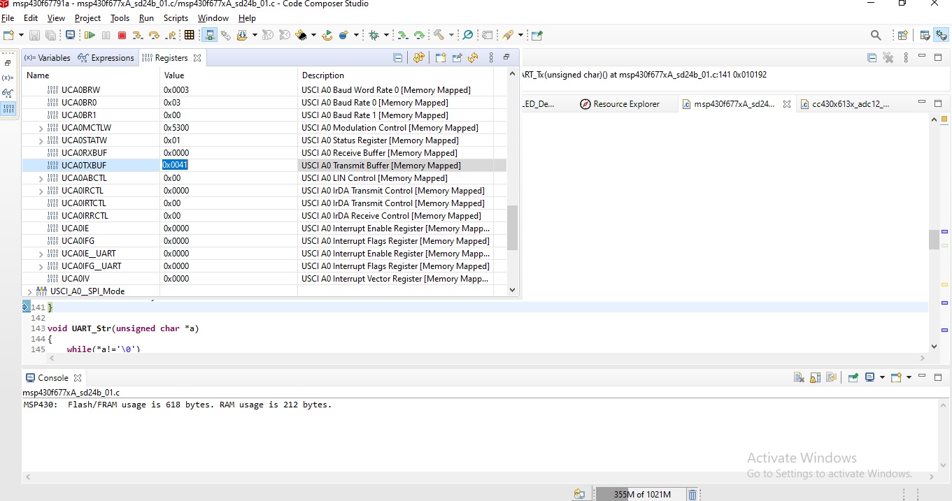
Part No : MSP430F67791A. We designed our own board for your reference circuit and also added a uart to the usb interface circuit (this circuit is working well). We are testing your uart example code(msp430f677xa_uscia0_uart_03.c). It doesn't transmit and receive data. but debug mode only one character is send in one time, then stopped this line(while (!(UCA0IFG & UCTXIFG));  but sd24 adc code is working well. here attached code and debug result. kindly reply soon.   Thank you.

#include <msp430.h>


void UART_init()
{
    // Setup P3.0 UCA0RXD, P3.1 UCA0TXD
       P3SEL0 |= BIT0 | BIT1;                   // Set P3.0, P3.1 to non-IO
       P3DIR |= BIT0 | BIT1;                   // Enable UCA0RXD, UCA0TXD

       // Setup LFXT1
       UCSCTL6 &= ~(XT1OFF);                   // XT1 On
       UCSCTL6 |= XCAP_3;                      // Internal load cap
       // Loop until XT1 fault flag is cleared
       do
       {
           UCSCTL7 &= ~(XT2OFFG | XT1LFOFFG | DCOFFG);
           // Clear XT2,XT1,DCO fault flags
           SFRIFG1 &= ~OFIFG;                  // Clear fault flags
       } while (SFRIFG1 & OFIFG);              // Test oscillator fault flag

       // Setup eUSCI_A0
       UCA0CTLW0 |= UCSWRST;                   // **Put state machine in reset**
       UCA0CTLW0 |= UCSSEL_1;                  // CLK = ACLK
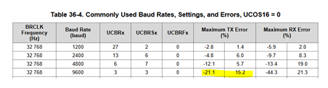
       UCA0BRW_L = 0x03;                       // 32kHz/9600=3.41 (see User's Guide)
       UCA0BRW_H = 0x00;                       //
       UCA0MCTLW = 0x5300;                     // Modulation UCBRSx=0x53, UCBRFx=0
       UCA0CTLW0 &= ~UCSWRST;                  // **Initialize USCI state machine**
     //  UCA0IE |= UCRXIE;                       // Enable USCI_A0 RX interrupt

    //   __bis_SR_register(LPM3_bits | GIE);     // Enter LPM3, interrupts enabled
    //   __no_operation();
}

void UART_Tx(unsigned char a)
{
    while (!(UCA0IFG & UCTXIFG));             // USCI_A0 TX buffer ready?
        UCA0TXBUF = a;
}

void UART_Str(unsigned char *a)
{
    while(*a!='\0')
        {
        UART_Tx(*a); a++;
        }
}


void main(void)
{
    int i=0;
    WDTCTL = WDTPW | WDTHOLD;               // Stop WDT
   
    UART_init();   

    while(1)
        {
        UART_Str("ABCD");
		
        }
}

  • Hi Siva,

    Your code works for me.  I can see "ABCD" repeated on the TXD pin.

    Now, I did discover that a 9600 baud rate sourced from a 32.768KHz clock is possible, it is not very accurate, as you can see from the table in the users guide.

    I don't know the device you are connected to but it's UART interface may not tolerate such as large error.  Typically 2-3% is acceptable.

    That may be why you don't see any data.  If you can, use either a logic probe or oscilloscope and verify you are sending the characters on the TXD pin.

  • Dear Sir,

    We are using  MSP430FR2475 and MSP430F67791A microcontrollers. UART Communication is debugging modes are working well but the serial monitor is not working. 
    I'm using a 32.768Khz external clock in MSP430FR2475(XIN - P2.1, XOUT -P2.0) and MSP430F67791A(PIN-1, PIN-2)
    Test with Oscilloscope,
    ACLK Pin - No signal is available (both Microcontroller)
    But,
    This example code (msp430fr2467x_CS_02.c) is working well. Now the ACLK pin is available at 32.768Khz and 3.3V Peak-Peak voltage(Oscilloscope tested). but uart code 
    how to switch on the external xtal in my uart code?
    Please reply to me.  
  • Hi Siva,

    You can output the F67791 ACLK on P1.2 and the FR2475 ACLK is on P2.2.

    I don't think the issue is the 32KHz clock.  The external xtal provides a very accurate frequency.  The problem is dividing the 32KHz frequency to meet the 9600 baud rate accuracy is what may be the issue.  To test this theory, change the baud rate to 1200 and see if the communications works. 

    Also, use the oscilloscope to look at the UART TXD signal.  Does it appear?  Can you take a picture?

**Attention** This is a public forum