This thread has been locked.

If you have a related question, please click the "Ask a related question" button in the top right corner. The newly created question will be automatically linked to this question.

MSP430FR5964: I2C peripheral start NACK timing

Part Number: MSP430FR5964

Dear Sir/Madam,

I am currently testing the UsciB in I2C mode, it seems that the peripheral does not behave as described in the manual.

Nor as described by others in this thread:

"e2e.ti.com/.../253933

I deliberately used the wrong address to test how the peripheral would respond.

As can be seen there is no ack on the 9th clock pulse, just some minor cross talk:

Looking at the code, it looks like this:

static bool i2cUsciB_startTransmit(I2cUsciBHardwareRegisters_t* pHardwareRegisters, uint8_t slaveAddress)
{    
    pHardwareRegisters->InterruptFlags = 0;
    
    pHardwareRegisters->SlaveAddress = slaveAddress;
    pHardwareRegisters->ControlWord0 |= UCTR_1;     /* Transmitter mode */    
    pHardwareRegisters->ControlWord0 |= UCTXSTT_1;  /* Generate START condition */   

    // Wait for the start condition to disappear
    while (pHardwareRegisters->ControlWord0 & UCTXSTT_1)
    {               
    }    
    
    uint16_t interruptFlags = pHardwareRegisters->InterruptFlags;

    //!!!!!!!!!!!!!!!!!!!!!!!!!!!!!!!!!!!!!!!!!!!!!!!!!!!!!!!!!!!!!!!!!!!!!!!!!!!!!!!!!!!!!!!!!!!!!!!!!!!!!!!!!!!!
    // WORKAROUND
    //!!!!!!!!!!!!!!!!!!!!!!!!!!!!!!!!!!!!!!!!!!!!!!!!!!!!!!!!!!!!!!!!!!!!!!!!!!!!!!!!!!!!!!!!!!!!!!!!!!!!!!!!!!!!
    uint16_t interruptFlagsFirstPass = interruptFlags;
    
    // If a slave has acknowledged UCNACKIFG_1 would be low
    for (int i = 0 ; i < 4 ; i++)
    {        
        interruptFlags = pHardwareRegisters->InterruptFlags;
    }       
    return (interruptFlags & UCNACKIFG_1) == 0;
}

The yellow area was added to debug what I have noticed...

According to the manual, at least my interpretation of it, the UCNACKIFG should be high directly after UCTXSTT has gone low:
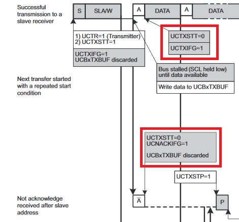
However when running the code I see that interruptFlagsFirstPass has the value 0x0002 and interruptFlags gets the value 0x0022 after going through the loop (at least) 4 times....

The NACK signal seems to be delayed...

I would prefer to solve this without using the loop, since I don't like the dependency between the speed of the cpu and the speed of the peripheral...

Hope that someone can help me further.

Thanks in advance,

Best regards,

Martin

  • Hi Martin,

    I don't know what frequency you have your CPU clocked at (I'll assume 8MHz) but at first glance I suspect the CPU is able to go through the loop a couple of times before the UCNACKIFG gets set, assuming also that your I2C clock is 400KHz.

    There is an I2C Master example code for this MSP430 that you can try the same experiment to see if you get the same results.  The example code expects there to be an I2C slave device but since you won't have one this is close to what you are attempting to demonstrate.

  • The thing that seems odd to me is that the I2C unit is presenting UCNACKIFG before you've put anything into TXBUF. Until then it won't release SCL ("stalled"), as seen in your scope trace. Until it releases SCL, there is no NACK.

    I suggest you store something into TXBUF, then read the interruptFlags.

  • Hi Martin,

    Checking to see if you have made any progress or if you still need assistance?

  • Hello Bruce,

    Thank you for your suggestion.

    Sorry for my late reply, had to work on another part of the project for a few weeks.

    Anyhow, I tried your suggestion, writing the first byte into the transmit buffer:

    static bool i2cUsciB_startTransmitRegisterAddress(I2cUsciBHardwareRegisters_t* pHardwareRegisters, uint8_t slaveAddress, uint8_t registerAddress)
    {    
        pHardwareRegisters->InterruptFlags = 0;
        
        pHardwareRegisters->SlaveAddress = slaveAddress;  
    
        pHardwareRegisters->ControlWord0 |= UCTR_1; /* Transmitter mode */    
        pHardwareRegisters->TransmitBuffer = registerAddress;  
        pHardwareRegisters->ControlWord0 |= UCTXSTT_1; /* Generate START condition */         
    
        // pHardwareRegisters->TransmitBuffer = registerAddress; // Also tried here
    
        // Wait for the start condition to disappear 
        while(pHardwareRegisters->ControlWord0 & UCTXSTT_1)
        {               
        }    
        
        uint16_t interruptFlags = pHardwareRegisters->InterruptFlags;
        
        //!!!!!!!!!!!!!!!!!!!!!!!!!!!!!!!!!!!!!!!!!!!!!!!!!!!!!!!!!!!!!!!!!!!!!!!!!!!!!!!!!!!!!!!!!!!!!!!!!!!!!!!!!!!!
        // WORKAROUND: There seems to be a bug in the I2C peripheral when no device acknowledges a start condition
        // UCNACKIFG is expected to be set in the InterruptFlags when UCTXSTT goes low. Added a few loops to make 
        // this work reliably.
        //!!!!!!!!!!!!!!!!!!!!!!!!!!!!!!!!!!!!!!!!!!!!!!!!!!!!!!!!!!!!!!!!!!!!!!!!!!!!!!!!!!!!!!!!!!!!!!!!!!!!!!!!!!!!
        uint16_t interruptFlagsFirstPass = interruptFlags;
        
        for (int i = 0; i < 4; i++)
        {        
            interruptFlags = pHardwareRegisters->InterruptFlags;
        }       
        // If a slave has acknowledged UCNACKIFG_1 would be low
        return (interruptFlags & UCNACKIFG_1) == 0;
    }

    Breaking at the return interruptFlagsFirstPass is 0x0002, interruptFlags = 0x0022, as such when UCTXSTT goes low the UCNACKIFG hasn't been updated yet.

    Note that I also tried two locations to write to the transmit buffer of the peripheral, the behavior did not change.

    The signals on the oscilloscope image are the same as before:

  • Hello Dennis,

    Thank you for your reply.

    My apologies for my late reply, had to work on another part of the project.

    You are correct, the cpu is clocked at 8Mhz and the communication speed is 400kHz.

    I did notice the example code, it uses an interrupt handler to keep the communication going.

    There are several reasons I did not want to use an interrupt handler.

    1. No need.
      Transfers will be infrequent and the amount of bytes to be transferred to/from I2C devices is really limited, the worst case transfer would take less than 1 ms, the main loop can block for such a short time.
    2. Code simplicity.
      Global buffers are required to transfer information to and from the interrupt handler.
      A typical read from devices requires a register address to be written before a read transfer can be started.
      Conditional behavior will creep into the interrupt handler, making it complex.
    3. I am forced to use VisualGDB for this project.
      It has the tendency to crash when putting a breakpoint in an interrupt handler :-(.

    Best regards,

    Martin Meijerman

**Attention** This is a public forum