This thread has been locked.

If you have a related question, please click the "Ask a related question" button in the top right corner. The newly created question will be automatically linked to this question.

CCS/MSP430F67791A: EMDC Generated code validation

Part Number: MSP430F67791A
Other Parts Discussed in Thread: MSP-EXP430F5529LP, MSP-ISO

Tool/software: Code Composer Studio

Dear Sir,

Part umber : MSP430F67791A

Code : EMDC Generated code

Baud rate  : 250Kbps 

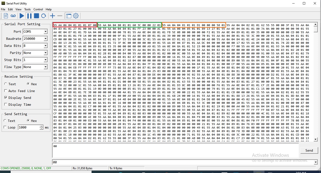
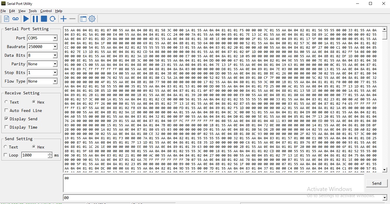
I want to read all parameters data from EMDC through uart communication. I sent to EMDC on following commands are 0x55,0xAA,0X06,0X04,0X01,0X01,0X01,0X07,0X00 and  EMDC reply the lot of data's.

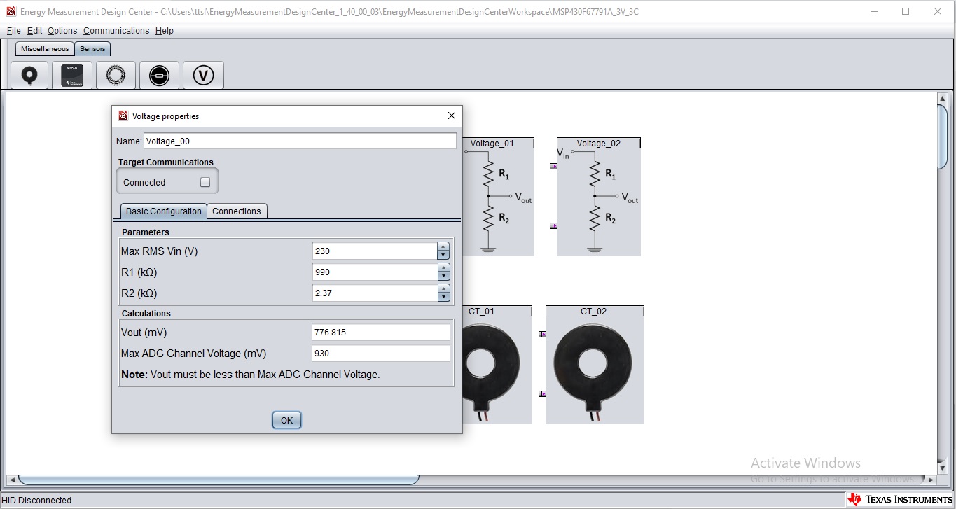
Example: Received Phase A data is 0x55,0xAA,0X0A,0X04,0X80,0X01,0X01,0X60,0X3C,0X00,0X00,0X22,0X01   =   230V (how to calculate) 

Now I connect Phase A only for input voltage 230V and output 542mV AC apply the SD0P0, SD0N0 pin in MSP430F67791A Mcu.  

here attached my result image. Kindly reply soon.

  • I think you can follow the communication protocol: 

  • Hi Eason Zhou

    Thanks for your valuable reply

    Communication Protocal Spec studied. but no idea for solve this problem (calculation).

    I prepared my own hardware for your reference circuit. 

    My hardware connection is,

    MSP430F67791A Circuit + TTL to usb converter circuit(It's support 250Kbps)

    I sent to EMDC on following commands are 0x55,0xAA,0X06,0X04,0X01,0X01,0X01,0X07,0X00 and  EMDC reply the lot of data's.

    example PHAS A RMS voltage data is,

    55 AA 0A 4 80 1 1 58 3C 0 0 1A 1

    Payload data's - 58 3C 0 0 1A 1   -  1A1+3c58 = 15730 (this is correct calculation or not) 

    how to calculate RMS voltage and others?

    Inputs:

    Voltage Sensor Unit:

    Phase A -input ; 230V output:542mV AC(voltage divider after)

    Phase B -input ; 230V output:542mV AC(voltage divider after)

    Phase C -input ; 230V output:542mV AC(voltage divider after)

    Current Sensor Unit:

    Load not connect to all Phases.

    here attached result excel and image.

    I want know the details,

    If received data's are correct or wrong?

    emdc result.xls

  • Only byte 7 to 10 is the data. That means 58 3C 0 0 is what you want.

    As Byte 7 is LSB.

    Then the voltage is 0x3C58. 15448mV.

  • Hi Eason Zhou

    Actually my input voltage is 230V AC and output is 542mV(Voltage divider circuit after).

    but  EMDC result voltage is 0x3C58. 15448mV. It is wrong voltage value.

    where is my mistake. here attached some EMDC GUI configuration images, Please reply soon.

    Thank You!

  • Actually, EMDC will convert the input directly to 230AC, that is the reason why you need to input the sensor parameters.

    15448mV equals to 15.448V. 

    My advice is that, first use EMDC GUI to test the whole product.

  • Hi Eason Zhou

    We are want to know the some details about this project

    1.We want to test EMDC GUI

    Your Hardware Connection is, 

    EVM430-F6779  + MSP-ISO + MSP-EXP430F5529LP

    Let me know the following Hardware connection is possible to communicate EMDC GUI

    MSP430-F67791A(MY OWN BOARD) +  MSP-ISO + MSP-EXP430F5529LP

    2.Let me know the details for following hardware connection is must need in final product,

    MSP430-F67791A(MY OWN BOARD) +  MSP-ISO + MSP-EXP430F5529LP

    Thank You!

  • 1. Actually, you only need: MSP430-F67791A(MY OWN BOARD) +  MSP-EXP430F5529LP for communication. MSP-ISO is used for protect F5529.

    2. For production, it depends on how you want to calibrate the E-meter, using EMDC GUI, or anything else. If you want to use EMDC, the hardware connection is must need in final product.

**Attention** This is a public forum