This thread has been locked.

If you have a related question, please click the "Ask a related question" button in the top right corner. The newly created question will be automatically linked to this question.

MSP430F47177: SPI Driver Initialization in MSP430F47177

Part Number: MSP430F47177
In one of our metering application, we need a SPI peripheral of MSP430F47177 microcontroller to communicate with the external IC.
We are using UCA1 channel for SPI communication . It is P1.6/UCA1TXD/UCA1SIMO,P1.7/UCA1RXD/UCA1SOMI & P2.0/UCB1STE/UCA1CLK.
 
Initilization routine is as follows :-
main()
{
P1SEL |= (BIT6 | BIT7);                                                                                  //select alternate peripheral function,  //Port 1.6 – USIA1-SIMO, Port-2.7 USCIA1-SOMI  
                                          
P2SEL |= BIT0;                                                                                               //Select USCIA0-SCLK 
UCA1CTL1 = UCSWRST;                                                                               // **Put state machine in reset**
UCA1CTL0 |= UCCKPH | UCMST | UCSYNC | UCMSB | UCMODE_0;        //3-pin, 8-bit SPI master, UCSYNC bit select synchronous mode (SPI Mode)
UCA1CTL1 |= UCSSEL_2;                                                                              // feed SMCLK to SPI SCLK
UCA1BR0 = 0x02;                                                                                           // SMCLK/2    
UCA1BR1 = 0;                                
   
 
UCA1MCTL = 0;                                                                                              // No modulation    
UCA1CTL1 &= ~UCSWRST;                                                                           // **Initialize USCI state machine**    
UC1IE |= UCA1RXIE;                                                                                      // Enable USCI_A1 RX interrupt  
}
After every 5 sec UCA1TXBUF is loaded with data to send it over SPI
But no data/clock is observed on SIMO/SOMI/SCLK pin.
We have already checked MSP430F47177 sample codes (available on TI Website).  The above configuration is as per sample code only.
Need your help in this regard. Is there any thing that we are missing something in configuration of SPI peripheral?
  • Hi,

    is this the complete code? Do you go into a LPM mode or stay in active mode? If you maybe go to LPM3 SMCLK might be turned off. In

    So the code example below should work for UCA0 and P2.4 and P2.5 and it only turns of CPU by going to LPM0. Is this maybe something you missed.

    From the Init I do not see a big issue assuming UCMODE_0 = represents 0x00 to really go into 3 pin mode. Maybe you can post the register settings (debug view register) once the TX buffer was filled.

    #include <msp430.h>

    unsigned char MST_Data,SLV_Data;
    int counter;
    int main(void)
    {
      volatile unsigned int i;

      WDTCTL = WDTPW+WDTHOLD;                   // Stop watchdog timer
      FLL_CTL0 |= XCAP11PF;                     // Configure load caps

      // Wait for xtal to stabilize
      do
      {
        IFG1 &= ~OFIFG;                           // Clear OSCFault flag
        for (i = 0x47FF; i > 0; i--);             // Time for flag to set
      }
      while ((IFG1 & OFIFG));                   // OSCFault flag still set?

      for(i=2100;i>0;i--);                      // Now with stable ACLK, wait for
                                                // DCO to stabilize.
      P5OUT = BIT2;                             // P5 setup for LED and slave reset
      P5DIR |= BIT1+BIT2;                            //

      P2SEL |= BIT4+BIT5;
      P3SEL |= BIT0;
      UCA0CTL0 |= UCMST+UCSYNC+UCCKPL+UCMSB;    //3-pin, 8-bit SPI master
      UCA0CTL1 |= UCSSEL_2;                     // SMCLK
      UCA0BR0 = 0x0F;                           // /2
      UCA0BR1 = 0;                              //
      UCA0MCTL = 0;                             // No modulation
      UCA0CTL1 &= ~UCSWRST;                     // **Initialize USCI state machine**
      IE2 |= UCA0RXIE;                          // Enable USCI_A0 RX interrupt

      P5OUT &= ~BIT2;                           // Now with SPI signals initialized,
      P5OUT |= BIT2;                            // reset slave

      for(i=5000;i>0;i--);                        // Wait for slave to initialize

      MST_Data = 0x001;                         // Initialize data values
      SLV_Data = 0x000;                         //

      UCA0TXBUF = MST_Data;                     // Transmit first character
     __bis_SR_register(LPM0_bits + GIE);       // CPU off, enable interrupts
    }

    #if defined(__TI_COMPILER_VERSION__) || defined(__IAR_SYSTEMS_ICC__)
    #pragma vector=USCIAB0RX_VECTOR
    __interrupt void USCIA0RX_ISR (void)
    #elif defined(__GNUC__)
    void __attribute__ ((interrupt(USCIAB0RX_VECTOR))) USCIA0RX_ISR (void)
    #else
    #error Compiler not supported!
    #endif
    {
      volatile unsigned int i;

      while (!(IFG2 & UCA0TXIFG));              // USART1 TX buffer ready?
      if (UCA0RXBUF==SLV_Data)                  // Test for correct character RX'd
        P5OUT |= BIT1;                          // If correct, light LED
      else
        P5OUT &= ~BIT1;                         // If incorrect, clear LED

      MST_Data++;                               // Increment data
      SLV_Data++;
      UCA0TXBUF = MST_Data;                     // Send next value

      for(i=30;i>0;i--);                        // Add time between transmissions to
    }   

  • Hi,

    did the post above helped to resolve your problem? If not please let us know otherwise I will close this thread latest by 12th February '21.

  • No. 

    It didn't resolved the issue.

    I can see SMCLK, but no SCLK

  • Hi,

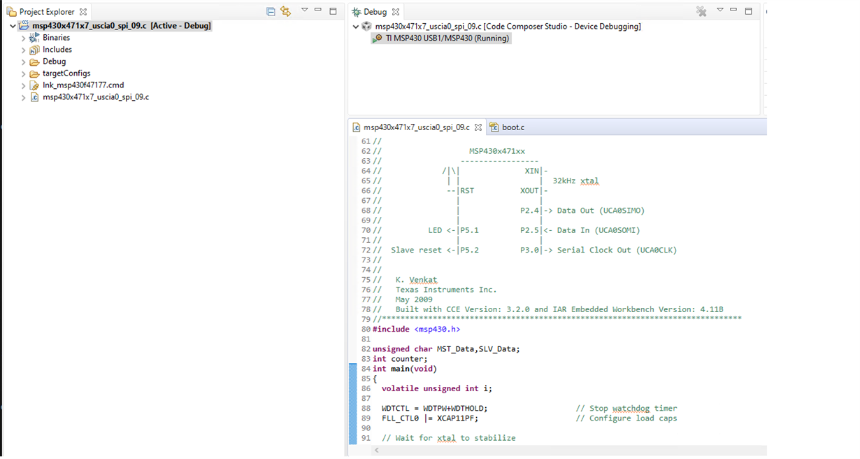
    today I programmed the spi_09 example on a F41777 example as shown below and I can see the data out and clock signals on the corresponding pins (put a scope shot below).

    Please check if the LFO crystal is connected and the jumps over the fault flag routine of the sample code. If this does not work post a picture of the HW setup.

  • Hi,

    did you had a chance to review my last post? Is there anything which can be done for your?

**Attention** This is a public forum