This thread has been locked.

If you have a related question, please click the "Ask a related question" button in the top right corner. The newly created question will be automatically linked to this question.

MSP430F5310: start up failures at Low temperatures

Part Number: MSP430F5310

Recently our production line is getting a 50% fallout rate during Low temperature functional test of the MSP430F5310IRGCR.

Our source code sets the core voltage before initializing the crystal or any of the clock configuration. Our system uses a 32.768kHz crystal and configures the clocking system to run at 24mHz. However, before initializing any of the clock registers the core voltage must incrementally be adjusted to 3.3V to run the clock at 24mHz. We have been in production for 3 years and have tested 14,000 units from -55C to +85C….just within the last several months run into this problem. At the cold temperatures, the code gets stuck in the routines that are increasing the core voltage to 3.3V, which, once again, this code happens before any clock configuration. 

In the past few months we have had MSP430F5310 processor get stuck at -40C, waiting for the SETVCoreUp function.  At power up, before running the MSP at 24MegHz we setup the core voltage to 3.3V.

We have tried modifying the code to see if the problem changes with no effect so we are thinking it may be hardware related.

Is anyone aware of cold startup issues with this product family?

What other tests can be run to narrow down the problem?

  • Hi Dwight,

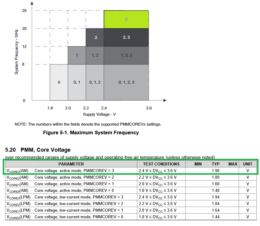
    so far TI is not aware of any cold start-up problems on these devices to better understand the phenomena we need some more details. First point I want to make here is that Vcore cannot be increased to 3.3V. I think you mean you increase it to Vcore level 3 to later on support 24 MHz and you do this at 3.3V DVCC supply correct?
    Finally you want to run the core LDO at around 1.9V to cover the green marked operating mode correct?

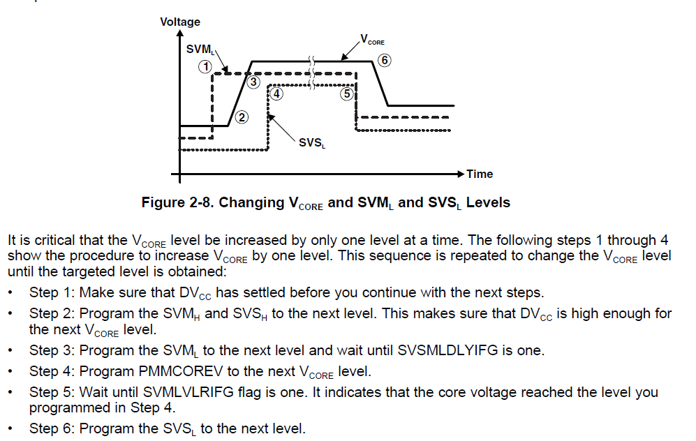
    This must be done step by step with respect to SVSH and SVSL increasing together as described in the user guide.

    Normally this Vcore increase is done by a TI driver function. Now to my questions:

    1. Do you use the TI driver to do this? Can you please post the Vcore increase code?

    2. Do you have an idea where in this Vcore increase functions it hangs? Maybe you can add a scope probe to DVCC and Vcore in good case you should see the step by step increase and then you can post good vs. fail to get an idea what goes wrong.

  • Yes the Vcore is set to 1.9V so that we can run at 24MHz.

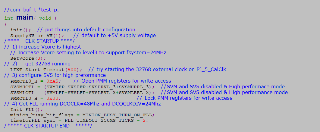
    Startup code included.

    We will attempt to probe the parts in the cold chamber to see where it hangs.

    here is a picture of the what we do from the start of main… the init() function disables the watchdog and initializes ports (I can share that code it they would like) and the Supply3V_or_5V(1) function is selecting the voltage level on DVIO pin for the MSP.  Our circuitry can regulate DVIO to either 3.3V or 5V.


    #include "main.h"
    #include <msp430F5172.h>
    
    #define PMM_STATUS_OK     0
    #define PMM_STATUS_ERROR  1
    #define VCORE_LOOP_DELAY 200000 
    
    /*******************************************************************************
     * \brief   Increase Vcore by one level
     *
     * \param level     Level to which Vcore needs to be increased
     * \return status   Success/failure
     ******************************************************************************/
    static uint16 SetVCoreUp(byte level)
    {
      uint16 PMMRIE_backup, SVSMHCTL_backup, SVSMLCTL_backup;
       
      // The code flow for increasing the Vcore has been altered to work around
      // the erratum FLASH37. 
      // Please refer to the Errata sheet to know if a specific device is affected
      // DO NOT ALTER THIS FUNCTION
    
      // Open PMM registers for write access   
      PMMCTL0_H = 0xA5;
      
      // Disable dedicated Interrupts
      // Backup all registers
      PMMRIE_backup = PMMRIE;
      PMMRIE &= ~(SVMHVLRPE | SVSHPE | SVMLVLRPE | SVSLPE | SVMHVLRIE |
            SVMHIE | SVSMHDLYIE | SVMLVLRIE | SVMLIE | SVSMLDLYIE );
      SVSMHCTL_backup = SVSMHCTL;
      SVSMLCTL_backup = SVSMLCTL;
    
      // Clear flags
      PMMIFG = 0;
    
      // Set SVM highside to new level and check if a VCore increase is possible
      SVSMHCTL = SVMHE | SVSHE | (SVSMHRRL0 * level);    
    
      // Wait until SVM highside is settled
    #if 1 /* add timeout  Oct 26, 2020 DLI*/
      Core_time_counter = 0;
      __delay_cycles(120);  // about 5 u seconds
      while ((PMMIFG & SVSMHDLYIFG) == 0) {
        if(Core_time_counter++ > VCORE_LOOP_DELAY)    // timeout delay
          WDTCTL = 0;  // something not working force a Reset to the minion system  
      } 
    #else
      while ((PMMIFG & SVSMHDLYIFG) == 0); 
    #endif
      // Clear flag
    
      // Clear flag
      PMMIFG &= ~SVSMHDLYIFG;
      
      // Check if a VCore increase is possible
      if ((PMMIFG & SVMHIFG) == SVMHIFG) {      // -> Vcc is too low for a Vcore increase
      	// recover the previous settings
      	PMMIFG &= ~SVSMHDLYIFG;
      	SVSMHCTL = SVSMHCTL_backup;
    
      	// Wait until SVM highside is settled
    #if 1 /* add timeout  Oct 26, 2020 DLI*/
        Core_time_counter = 0;
        __delay_cycles(120);  // about 5 u seconds
        while ((PMMIFG & SVSMHDLYIFG) == 0) {
          if(Core_time_counter++ > VCORE_LOOP_DELAY)   // timeout delay
            WDTCTL = 0;  // something not working force a Reset to the mionion system  
        } 
    #else
        while ((PMMIFG & SVSMHDLYIFG) == 0); 
    #endif
    
      	// Clear all Flags
      	PMMIFG &= ~(SVMHVLRIFG | SVMHIFG | SVSMHDLYIFG | SVMLVLRIFG | SVMLIFG | SVSMLDLYIFG);
    
      	PMMRIE = PMMRIE_backup;                 // Restore PMM interrupt enable register
      	PMMCTL0_H = 0x00;                       // Lock PMM registers for write access
      	return PMM_STATUS_ERROR;                // return: voltage not set
      }
      
      // Set also SVS highside to new level	    
      // Vcc is high enough for a Vcore increase
      SVSMHCTL |= (SVSHRVL0 * level);
    
      // Wait until SVM highside is settled
    #if 1 /* add timeout  Oct 26, 2020 DLI*/
      Core_time_counter = 0;
      __delay_cycles(120);  // about 5 u seconds
      while ((PMMIFG & SVSMHDLYIFG) == 0) {
        if(Core_time_counter++ > VCORE_LOOP_DELAY)    // timeout delay
          WDTCTL = 0;  // something not working force a Reset to the minion system  
      } 
    #else
      while ((PMMIFG & SVSMHDLYIFG) == 0);    
    #endif   
    
      // Clear flag
      PMMIFG &= ~SVSMHDLYIFG;
      
      // Set VCore to new level
      PMMCTL0_L = PMMCOREV0 * level;
    
      // Set SVM, SVS low side to new level
      SVSMLCTL = SVMLE | (SVSMLRRL0 * level) | SVSLE | (SVSLRVL0 * level);
    
      // Wait until SVM, SVS low side is settled
    #if 1 /* add timeout  Oct 26, 2020 DLI*/
      Core_time_counter = 0;
      __delay_cycles(120);  // about 5 u seconds
      while ((PMMIFG & SVSMLDLYIFG) == 0) {
        if(Core_time_counter++ > VCORE_LOOP_DELAY)    // timeout delay
          WDTCTL = 0;  // something not working force a Reset to the minion system  
      } 
    #else
      while ((PMMIFG & SVSMLDLYIFG) == 0);
    #endif
    
      // Clear flag
      PMMIFG &= ~SVSMLDLYIFG;
      // SVS, SVM core and high side are now set to protect for the new core level
      
      // Restore Low side settings
      // Clear all other bits _except_ level settings
      SVSMLCTL &= (SVSLRVL0+SVSLRVL1+SVSMLRRL0+SVSMLRRL1+SVSMLRRL2);
    
      // Clear level settings in the backup register,keep all other bits
      SVSMLCTL_backup &= ~(SVSLRVL0+SVSLRVL1+SVSMLRRL0+SVSMLRRL1+SVSMLRRL2);
      
      // Restore low-side SVS monitor settings
      SVSMLCTL |= SVSMLCTL_backup;
      
      // Restore High side settings
      // Clear all other bits except level settings
      SVSMHCTL &= (SVSHRVL0+SVSHRVL1+SVSMHRRL0+SVSMHRRL1+SVSMHRRL2);
    
      // Clear level settings in the backup register,keep all other bits
      SVSMHCTL_backup &= ~(SVSHRVL0+SVSHRVL1+SVSMHRRL0+SVSMHRRL1+SVSMHRRL2);
    
      // Restore backup 
      SVSMHCTL |= SVSMHCTL_backup;
      
      // Wait until high side, low side settled
    #if 1 /* add timeout  Oct 26, 2020 DLI*/
      Core_time_counter = 0;
      __delay_cycles(120);  // about 5 u seconds
      while (((PMMIFG & SVSMLDLYIFG) == 0) && ((PMMIFG & SVSMHDLYIFG) == 0)) {
        if(Core_time_counter++ > VCORE_LOOP_DELAY)    // timeout delay
          WDTCTL = 0;  // something not working force a Reset to the minion system  
      } 
    #else
      while (((PMMIFG & SVSMLDLYIFG) == 0) && ((PMMIFG & SVSMHDLYIFG) == 0));
    #endif
    
      // Clear all Flags
      PMMIFG &= ~(SVMHVLRIFG | SVMHIFG | SVSMHDLYIFG | SVMLVLRIFG | SVMLIFG | SVSMLDLYIFG);
    
      PMMRIE = PMMRIE_backup;                   // Restore PMM interrupt enable register
      PMMCTL0_H = 0x00;                         // Lock PMM registers for write access
    
      return PMM_STATUS_OK;  
    }
    
    /*******************************************************************************
     * \brief  Decrease Vcore by one level
     *
     * \param  level    Level to which Vcore needs to be decreased
     * \return status   Success/failure
     ******************************************************************************/
    static uint16 SetVCoreDown(byte level)
    {
      uint16 PMMRIE_backup, SVSMHCTL_backup, SVSMLCTL_backup;
      
      // The code flow for decreasing the Vcore has been altered to work around
      // the erratum FLASH37. 
      // Please refer to the Errata sheet to know if a specific device is affected
      // DO NOT ALTER THIS FUNCTION
      
      // Open PMM registers for write access
      PMMCTL0_H = 0xA5;
    
      // Disable dedicated Interrupts 
      // Backup all registers
      PMMRIE_backup = PMMRIE;
      PMMRIE &= ~(SVMHVLRPE | SVSHPE | SVMLVLRPE | SVSLPE | SVMHVLRIE |
            SVMHIE | SVSMHDLYIE | SVMLVLRIE | SVMLIE | SVSMLDLYIE );
      SVSMHCTL_backup = SVSMHCTL;
      SVSMLCTL_backup = SVSMLCTL;
    
      // Clear flags
      PMMIFG &= ~(SVMHIFG | SVSMHDLYIFG | SVMLIFG | SVSMLDLYIFG);
      
      // Set SVM, SVS high & low side to new settings in normal mode
      SVSMHCTL = SVMHE | (SVSMHRRL0 * level) | SVSHE | (SVSHRVL0 * level);
      SVSMLCTL = SVMLE | (SVSMLRRL0 * level) | SVSLE | (SVSLRVL0 * level);
      
      // Wait until SVM high side and SVM low side is settled
    #if 1  /* add timeout  Oct 26, 2020 DLI*/
      Core_time_counter = 0;
      __delay_cycles(120);  // about 5 u seconds
      while ((PMMIFG & SVSMHDLYIFG) == 0 || (PMMIFG & SVSMLDLYIFG) == 0) {
        if(Core_time_counter++ > VCORE_LOOP_DELAY)    // timeout delay
          WDTCTL = 0;  // something not working force a Reset to the minion system  
      } 
    #else
      while ((PMMIFG & SVSMHDLYIFG) == 0 || (PMMIFG & SVSMLDLYIFG) == 0);
    #endif  
      
      // Clear flags
      PMMIFG &= ~(SVSMHDLYIFG + SVSMLDLYIFG);
      // SVS, SVM core and high side are now set to protect for the new core level
      
      // Set VCore to new level
      PMMCTL0_L = PMMCOREV0 * level;
      
      // Restore Low side settings
      // Clear all other bits _except_ level settings
      SVSMLCTL &= (SVSLRVL0+SVSLRVL1+SVSMLRRL0+SVSMLRRL1+SVSMLRRL2);
      
      // Clear level settings in the backup register,keep all other bits
      SVSMLCTL_backup &= ~(SVSLRVL0+SVSLRVL1+SVSMLRRL0+SVSMLRRL1+SVSMLRRL2);
      
      // Restore low-side SVS monitor settings
      SVSMLCTL |= SVSMLCTL_backup;
      
      // Restore High side settings
      // Clear all other bits except level settings
      SVSMHCTL &= (SVSHRVL0+SVSHRVL1+SVSMHRRL0+SVSMHRRL1+SVSMHRRL2);
      
      // Clear level settings in the backup register, keep all other bits
      SVSMHCTL_backup &= ~(SVSHRVL0+SVSHRVL1+SVSMHRRL0+SVSMHRRL1+SVSMHRRL2);
      
      // Restore backup 
      SVSMHCTL |= SVSMHCTL_backup;
      
      // Wait until high side, low side settled
    #if 1 /* add timeout  Oct 26, 2020 DLI*/
      Core_time_counter = 0;
      __delay_cycles(120);  // about 5 u seconds
      while (((PMMIFG & SVSMLDLYIFG) == 0) && ((PMMIFG & SVSMHDLYIFG) == 0)) {
        if(Core_time_counter++ > VCORE_LOOP_DELAY)    // timeout delay
          WDTCTL = 0;  // something not working force a Reset to the minon system  
      } 
    #else
      while (((PMMIFG & SVSMLDLYIFG) == 0) && ((PMMIFG & SVSMHDLYIFG) == 0));	
    #endif
      
      // Clear all Flags
      PMMIFG &= ~(SVMHVLRIFG | SVMHIFG | SVSMHDLYIFG | SVMLVLRIFG | SVMLIFG | SVSMLDLYIFG);
      
      PMMRIE = PMMRIE_backup;                   // Restore PMM interrupt enable register
      PMMCTL0_H = 0x00;                         // Lock PMM registers for write access
      return PMM_STATUS_OK;		                // Return: OK
    }
    
    uint16 SetVCore(byte level)
    {
      uint16 actlevel;
      uint16 status = 0;
    
      General_TimeOutCnt = 0;
      level &= PMMCOREV_3;                       // Set Mask for Max. level
      actlevel = (PMMCTL0 & PMMCOREV_3);         // Get actual VCore
                                                 // step by step increase or decrease
      while (((level != actlevel) && (status == 0)) || (level < actlevel)) {
        if (level > actlevel) {
          status = SetVCoreUp(++actlevel);
        }
        else {
          status = SetVCoreDown(--actlevel);
        }
    #if 1  /* add timeout  Oct 26, 2020 DLI*/
        __delay_cycles(120);  // about 5 u seconds
        if(General_TimeOutCnt++ > 400000)    // if greater than 2 seconds then force a watchdog
          WDTCTL = 0;  // something not working force a Reset to the RTC system  
    #endif
      }
      
      return status;
    }
    
    #if 0
    void SetVCoreUp (unsigned int level)
    {
      // Open PMM registers for write
      PMMCTL0_H = PMMPW_H;   
    
      SVSMHCTL = (SVMHFP+SVSHFP);  //High performace and SVM and SVS disabled 
    
      // Set SVS/SVM high side new level, with full performance mode
     // SVSMHCTL = (SVMHFP+SVSHFP) + SVSHE + SVSHRVL0 * level + SVMHE + SVSMHRRL0 * level;
      // Set SVM low side to new level, with full performance mode
    
      SVSMLCTL = (SVMLFP+SVSLFP);  //High performance mode SVM and SVS disabled  
     // SVSMLCTL = (SVMLFP+SVSLFP) + SVSLE + SVMLE + SVSMLRRL0 * level;
      // Wait till SVM is settled
     // while ((PMMIFG & SVSMLDLYIFG) == 0);
      // Clear already set flags
    
      PMMIFG &= ~(SVMLVLRIFG + SVMLIFG);
      // Set VCore to new level
      PMMCTL0_L = PMMCOREV0 * level;
      // Wait till new level reached
      if ((PMMIFG & SVMLIFG))
        while ((PMMIFG & SVMLVLRIFG) == 0);
      // Set SVS/SVM low side to new level, with full performance mode
    //  SVSMLCTL = SVSLE + SVSLRVL0 * level + SVMLE + SVSMLRRL0 * level;
      // Lock PMM registers for write access
      PMMCTL0_H = 0x00;
    }
    #endif
    

  • Dwight,

    so far so good you're using the DriverLib function to increase Vcore which is good. Do you know which version of the DriverLib you use? Where there any changes on your site?

    If I got it right you're pretty sure the problem appears in the "SetVCore(3)" call right? So you can exclude the LFXT start function, the SVS config or the FLL init?

    To confirm this I want to see the Vcore steps on a scope to see that it really goes trough all the 4 Vcore levels correctly. Also a port toggle after the Vcore increase would be a confirmation that it works.

    You mentioned the DVIO option; did it make a difference if you power DVIO with 3.3 or 5V?

  • Hi Dwight,

    any update on the requests above?

  • Dietmar

    Sorry for the slow responses.   I work for Arrow and am supporting an end customer.  They recently informed me that the problem went away when they got parts from a newer Lot code.  I have submitted those Lot code numbers to the internal support people.   

    Here is some more feedback from the customer.

    I’m pretty sure it gets stuck in the SetVCore(3)… But have not verified that with a scope and port pin like described by Dietmer… Again, this all happens at -40C so I will need to have cabling outside the chamber to capture Vcore steps etc.


    The way that I know it was in the SetVCore(3) function is that my code associated with the crystal startup and FLL has timeouts in the code that would force a reset.  We never get a reset and the SetVCore(3) was the only code that has while(1) loops with no timeouts.   Our latest code revision does have timeouts in the SetVCore(3), that did help but we still have some number of units failing, even though the system resets over and over again.


  • Hi Dwight,

    no problem. So the conclusion from customer make sense. However it would be great to see at which Vcore level it stops. Anyway can you pls help to get the following questions answered:

    1. Do you know which version of the DriverLib you use? Where there any changes on your site? Also maybe pls post the content of the Vcore increase function.
    2. You mentioned the DVIO option; did it make a difference if you power DVIO with 3.3 or 5V?

    It is important to ensure that the Vcore step up function is written properly, considering all the latest ERRATAs!

  • #include "main.h"
    #include <msp430F5172.h>
    
    #define PMM_STATUS_OK     0
    #define PMM_STATUS_ERROR  1
    #define VCORE_LOOP_DELAY 200000 
    
    /*******************************************************************************
     * \brief   Increase Vcore by one level
     *
     * \param level     Level to which Vcore needs to be increased
     * \return status   Success/failure
     ******************************************************************************/
    static uint16 SetVCoreUp(byte level)
    {
      uint16 PMMRIE_backup, SVSMHCTL_backup, SVSMLCTL_backup;
       
      // The code flow for increasing the Vcore has been altered to work around
      // the erratum FLASH37. 
      // Please refer to the Errata sheet to know if a specific device is affected
      // DO NOT ALTER THIS FUNCTION
    
      // Open PMM registers for write access   
      PMMCTL0_H = 0xA5;
      
      // Disable dedicated Interrupts
      // Backup all registers
      PMMRIE_backup = PMMRIE;
      PMMRIE &= ~(SVMHVLRPE | SVSHPE | SVMLVLRPE | SVSLPE | SVMHVLRIE |
            SVMHIE | SVSMHDLYIE | SVMLVLRIE | SVMLIE | SVSMLDLYIE );
      SVSMHCTL_backup = SVSMHCTL;
      SVSMLCTL_backup = SVSMLCTL;
    
      // Clear flags
      PMMIFG = 0;
    
      // Set SVM highside to new level and check if a VCore increase is possible
      SVSMHCTL = SVMHE | SVSHE | (SVSMHRRL0 * level);    
    
      // Wait until SVM highside is settled
    #if 1 /* add timeout  Oct 26, 2020 DLI*/
      Core_time_counter = 0;
      __delay_cycles(120);  // about 5 u seconds
      while ((PMMIFG & SVSMHDLYIFG) == 0) {
        if(Core_time_counter++ > VCORE_LOOP_DELAY)    // timeout delay
          WDTCTL = 0;  // something not working force a Reset to the minion system  
      } 
    #else
      while ((PMMIFG & SVSMHDLYIFG) == 0); 
    #endif
      // Clear flag
    
      // Clear flag
      PMMIFG &= ~SVSMHDLYIFG;
      
      // Check if a VCore increase is possible
      if ((PMMIFG & SVMHIFG) == SVMHIFG) {      // -> Vcc is too low for a Vcore increase
      	// recover the previous settings
      	PMMIFG &= ~SVSMHDLYIFG;
      	SVSMHCTL = SVSMHCTL_backup;
    
      	// Wait until SVM highside is settled
    #if 1 /* add timeout  Oct 26, 2020 DLI*/
        Core_time_counter = 0;
        __delay_cycles(120);  // about 5 u seconds
        while ((PMMIFG & SVSMHDLYIFG) == 0) {
          if(Core_time_counter++ > VCORE_LOOP_DELAY)   // timeout delay
            WDTCTL = 0;  // something not working force a Reset to the mionion system  
        } 
    #else
        while ((PMMIFG & SVSMHDLYIFG) == 0); 
    #endif
    
      	// Clear all Flags
      	PMMIFG &= ~(SVMHVLRIFG | SVMHIFG | SVSMHDLYIFG | SVMLVLRIFG | SVMLIFG | SVSMLDLYIFG);
    
      	PMMRIE = PMMRIE_backup;                 // Restore PMM interrupt enable register
      	PMMCTL0_H = 0x00;                       // Lock PMM registers for write access
      	return PMM_STATUS_ERROR;                // return: voltage not set
      }
      
      // Set also SVS highside to new level	    
      // Vcc is high enough for a Vcore increase
      SVSMHCTL |= (SVSHRVL0 * level);
    
      // Wait until SVM highside is settled
    #if 1 /* add timeout  Oct 26, 2020 DLI*/
      Core_time_counter = 0;
      __delay_cycles(120);  // about 5 u seconds
      while ((PMMIFG & SVSMHDLYIFG) == 0) {
        if(Core_time_counter++ > VCORE_LOOP_DELAY)    // timeout delay
          WDTCTL = 0;  // something not working force a Reset to the minion system  
      } 
    #else
      while ((PMMIFG & SVSMHDLYIFG) == 0);    
    #endif   
    
      // Clear flag
      PMMIFG &= ~SVSMHDLYIFG;
      
      // Set VCore to new level
      PMMCTL0_L = PMMCOREV0 * level;
    
      // Set SVM, SVS low side to new level
      SVSMLCTL = SVMLE | (SVSMLRRL0 * level) | SVSLE | (SVSLRVL0 * level);
    
      // Wait until SVM, SVS low side is settled
    #if 1 /* add timeout  Oct 26, 2020 DLI*/
      Core_time_counter = 0;
      __delay_cycles(120);  // about 5 u seconds
      while ((PMMIFG & SVSMLDLYIFG) == 0) {
        if(Core_time_counter++ > VCORE_LOOP_DELAY)    // timeout delay
          WDTCTL = 0;  // something not working force a Reset to the minion system  
      } 
    #else
      while ((PMMIFG & SVSMLDLYIFG) == 0);
    #endif
    
      // Clear flag
      PMMIFG &= ~SVSMLDLYIFG;
      // SVS, SVM core and high side are now set to protect for the new core level
      
      // Restore Low side settings
      // Clear all other bits _except_ level settings
      SVSMLCTL &= (SVSLRVL0+SVSLRVL1+SVSMLRRL0+SVSMLRRL1+SVSMLRRL2);
    
      // Clear level settings in the backup register,keep all other bits
      SVSMLCTL_backup &= ~(SVSLRVL0+SVSLRVL1+SVSMLRRL0+SVSMLRRL1+SVSMLRRL2);
      
      // Restore low-side SVS monitor settings
      SVSMLCTL |= SVSMLCTL_backup;
      
      // Restore High side settings
      // Clear all other bits except level settings
      SVSMHCTL &= (SVSHRVL0+SVSHRVL1+SVSMHRRL0+SVSMHRRL1+SVSMHRRL2);
    
      // Clear level settings in the backup register,keep all other bits
      SVSMHCTL_backup &= ~(SVSHRVL0+SVSHRVL1+SVSMHRRL0+SVSMHRRL1+SVSMHRRL2);
    
      // Restore backup 
      SVSMHCTL |= SVSMHCTL_backup;
      
      // Wait until high side, low side settled
    #if 1 /* add timeout  Oct 26, 2020 DLI*/
      Core_time_counter = 0;
      __delay_cycles(120);  // about 5 u seconds
      while (((PMMIFG & SVSMLDLYIFG) == 0) && ((PMMIFG & SVSMHDLYIFG) == 0)) {
        if(Core_time_counter++ > VCORE_LOOP_DELAY)    // timeout delay
          WDTCTL = 0;  // something not working force a Reset to the minion system  
      } 
    #else
      while (((PMMIFG & SVSMLDLYIFG) == 0) && ((PMMIFG & SVSMHDLYIFG) == 0));
    #endif
    
      // Clear all Flags
      PMMIFG &= ~(SVMHVLRIFG | SVMHIFG | SVSMHDLYIFG | SVMLVLRIFG | SVMLIFG | SVSMLDLYIFG);
    
      PMMRIE = PMMRIE_backup;                   // Restore PMM interrupt enable register
      PMMCTL0_H = 0x00;                         // Lock PMM registers for write access
    
      return PMM_STATUS_OK;  
    }
    
    /*******************************************************************************
     * \brief  Decrease Vcore by one level
     *
     * \param  level    Level to which Vcore needs to be decreased
     * \return status   Success/failure
     ******************************************************************************/
    static uint16 SetVCoreDown(byte level)
    {
      uint16 PMMRIE_backup, SVSMHCTL_backup, SVSMLCTL_backup;
      
      // The code flow for decreasing the Vcore has been altered to work around
      // the erratum FLASH37. 
      // Please refer to the Errata sheet to know if a specific device is affected
      // DO NOT ALTER THIS FUNCTION
      
      // Open PMM registers for write access
      PMMCTL0_H = 0xA5;
    
      // Disable dedicated Interrupts 
      // Backup all registers
      PMMRIE_backup = PMMRIE;
      PMMRIE &= ~(SVMHVLRPE | SVSHPE | SVMLVLRPE | SVSLPE | SVMHVLRIE |
            SVMHIE | SVSMHDLYIE | SVMLVLRIE | SVMLIE | SVSMLDLYIE );
      SVSMHCTL_backup = SVSMHCTL;
      SVSMLCTL_backup = SVSMLCTL;
    
      // Clear flags
      PMMIFG &= ~(SVMHIFG | SVSMHDLYIFG | SVMLIFG | SVSMLDLYIFG);
      
      // Set SVM, SVS high & low side to new settings in normal mode
      SVSMHCTL = SVMHE | (SVSMHRRL0 * level) | SVSHE | (SVSHRVL0 * level);
      SVSMLCTL = SVMLE | (SVSMLRRL0 * level) | SVSLE | (SVSLRVL0 * level);
      
      // Wait until SVM high side and SVM low side is settled
    #if 1  /* add timeout  Oct 26, 2020 DLI*/
      Core_time_counter = 0;
      __delay_cycles(120);  // about 5 u seconds
      while ((PMMIFG & SVSMHDLYIFG) == 0 || (PMMIFG & SVSMLDLYIFG) == 0) {
        if(Core_time_counter++ > VCORE_LOOP_DELAY)    // timeout delay
          WDTCTL = 0;  // something not working force a Reset to the minion system  
      } 
    #else
      while ((PMMIFG & SVSMHDLYIFG) == 0 || (PMMIFG & SVSMLDLYIFG) == 0);
    #endif  
      
      // Clear flags
      PMMIFG &= ~(SVSMHDLYIFG + SVSMLDLYIFG);
      // SVS, SVM core and high side are now set to protect for the new core level
      
      // Set VCore to new level
      PMMCTL0_L = PMMCOREV0 * level;
      
      // Restore Low side settings
      // Clear all other bits _except_ level settings
      SVSMLCTL &= (SVSLRVL0+SVSLRVL1+SVSMLRRL0+SVSMLRRL1+SVSMLRRL2);
      
      // Clear level settings in the backup register,keep all other bits
      SVSMLCTL_backup &= ~(SVSLRVL0+SVSLRVL1+SVSMLRRL0+SVSMLRRL1+SVSMLRRL2);
      
      // Restore low-side SVS monitor settings
      SVSMLCTL |= SVSMLCTL_backup;
      
      // Restore High side settings
      // Clear all other bits except level settings
      SVSMHCTL &= (SVSHRVL0+SVSHRVL1+SVSMHRRL0+SVSMHRRL1+SVSMHRRL2);
      
      // Clear level settings in the backup register, keep all other bits
      SVSMHCTL_backup &= ~(SVSHRVL0+SVSHRVL1+SVSMHRRL0+SVSMHRRL1+SVSMHRRL2);
      
      // Restore backup 
      SVSMHCTL |= SVSMHCTL_backup;
      
      // Wait until high side, low side settled
    #if 1 /* add timeout  Oct 26, 2020 DLI*/
      Core_time_counter = 0;
      __delay_cycles(120);  // about 5 u seconds
      while (((PMMIFG & SVSMLDLYIFG) == 0) && ((PMMIFG & SVSMHDLYIFG) == 0)) {
        if(Core_time_counter++ > VCORE_LOOP_DELAY)    // timeout delay
          WDTCTL = 0;  // something not working force a Reset to the minon system  
      } 
    #else
      while (((PMMIFG & SVSMLDLYIFG) == 0) && ((PMMIFG & SVSMHDLYIFG) == 0));	
    #endif
      
      // Clear all Flags
      PMMIFG &= ~(SVMHVLRIFG | SVMHIFG | SVSMHDLYIFG | SVMLVLRIFG | SVMLIFG | SVSMLDLYIFG);
      
      PMMRIE = PMMRIE_backup;                   // Restore PMM interrupt enable register
      PMMCTL0_H = 0x00;                         // Lock PMM registers for write access
      return PMM_STATUS_OK;		                // Return: OK
    }
    
    uint16 SetVCore(byte level)
    {
      uint16 actlevel;
      uint16 status = 0;
    
      General_TimeOutCnt = 0;
      level &= PMMCOREV_3;                       // Set Mask for Max. level
      actlevel = (PMMCTL0 & PMMCOREV_3);         // Get actual VCore
                                                 // step by step increase or decrease
      while (((level != actlevel) && (status == 0)) || (level < actlevel)) {
        if (level > actlevel) {
          status = SetVCoreUp(++actlevel);
        }
        else {
          status = SetVCoreDown(--actlevel);
        }
    #if 1  /* add timeout  Oct 26, 2020 DLI*/
        __delay_cycles(120);  // about 5 u seconds
        if(General_TimeOutCnt++ > 400000)    // if greater than 2 seconds then force a watchdog
          WDTCTL = 0;  // something not working force a Reset to the RTC system  
    #endif
      }
      
      return status;
    }
    
    #if 0
    void SetVCoreUp (unsigned int level)
    {
      // Open PMM registers for write
      PMMCTL0_H = PMMPW_H;   
    
      SVSMHCTL = (SVMHFP+SVSHFP);  //High performace and SVM and SVS disabled 
    
      // Set SVS/SVM high side new level, with full performance mode
     // SVSMHCTL = (SVMHFP+SVSHFP) + SVSHE + SVSHRVL0 * level + SVMHE + SVSMHRRL0 * level;
      // Set SVM low side to new level, with full performance mode
    
      SVSMLCTL = (SVMLFP+SVSLFP);  //High performance mode SVM and SVS disabled  
     // SVSMLCTL = (SVMLFP+SVSLFP) + SVSLE + SVMLE + SVSMLRRL0 * level;
      // Wait till SVM is settled
     // while ((PMMIFG & SVSMLDLYIFG) == 0);
      // Clear already set flags
    
      PMMIFG &= ~(SVMLVLRIFG + SVMLIFG);
      // Set VCore to new level
      PMMCTL0_L = PMMCOREV0 * level;
      // Wait till new level reached
      if ((PMMIFG & SVMLIFG))
        while ((PMMIFG & SVMLVLRIFG) == 0);
      // Set SVS/SVM low side to new level, with full performance mode
    //  SVSMLCTL = SVSLE + SVSLRVL0 * level + SVMLE + SVSMLRRL0 * level;
      // Lock PMM registers for write access
      PMMCTL0_H = 0x00;
    }
    #endif
    

    Let me know if this helps..

    I will check on the affects of 3.3 vs 5v DVIO

  • Thanks this looks good!

    I think it is really essential to trace DVCC, RST and VCORE if it appears to see at which level it hangs and if any event on DVCC or RST appears while Vcore is increased. Even if hard I think this is the best way to better understand this.

  • Sorry Dewight and Dietmar.... I may have confused things with the snippet of code that was setting 5V or 3.3V.  I have two different MSP processor in our product and the snippet of code was from the a different MSP that is not exhibiting the problem.  That MPU was the MSP5172 which has a DVIO that can run at either 5V or 3.3V on its IO. 

    However, the code in the the MSP5310 (which does have the start up issue) is very similar in that the clock, FLL and PMM are all after the SetVCore(3) function and the SetVCore routines are an old version of TI's code that I copied serval years ago.  

    I'm working on getting the scope captures as requested by Dietmar hope to post that within the next day or so.

    thanks for your help on this issue

  • Ok have the captures....

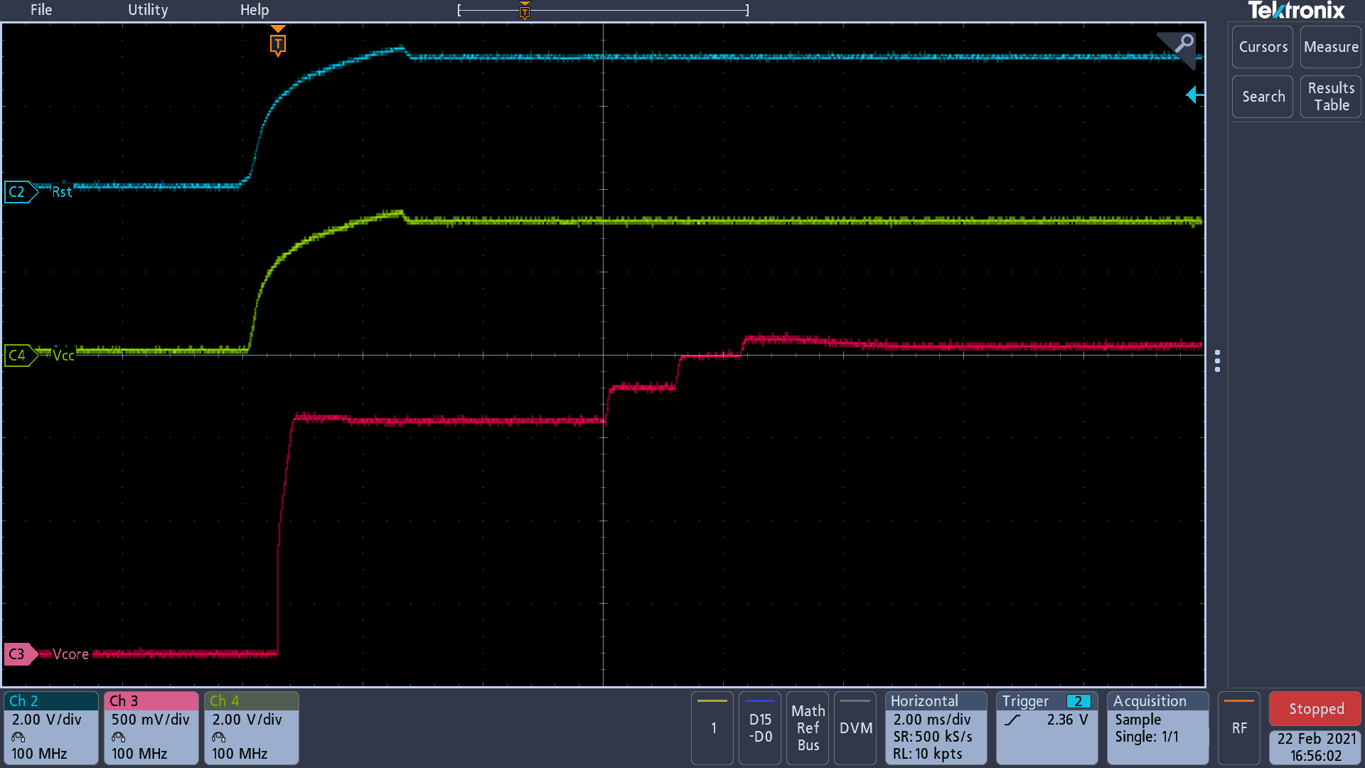
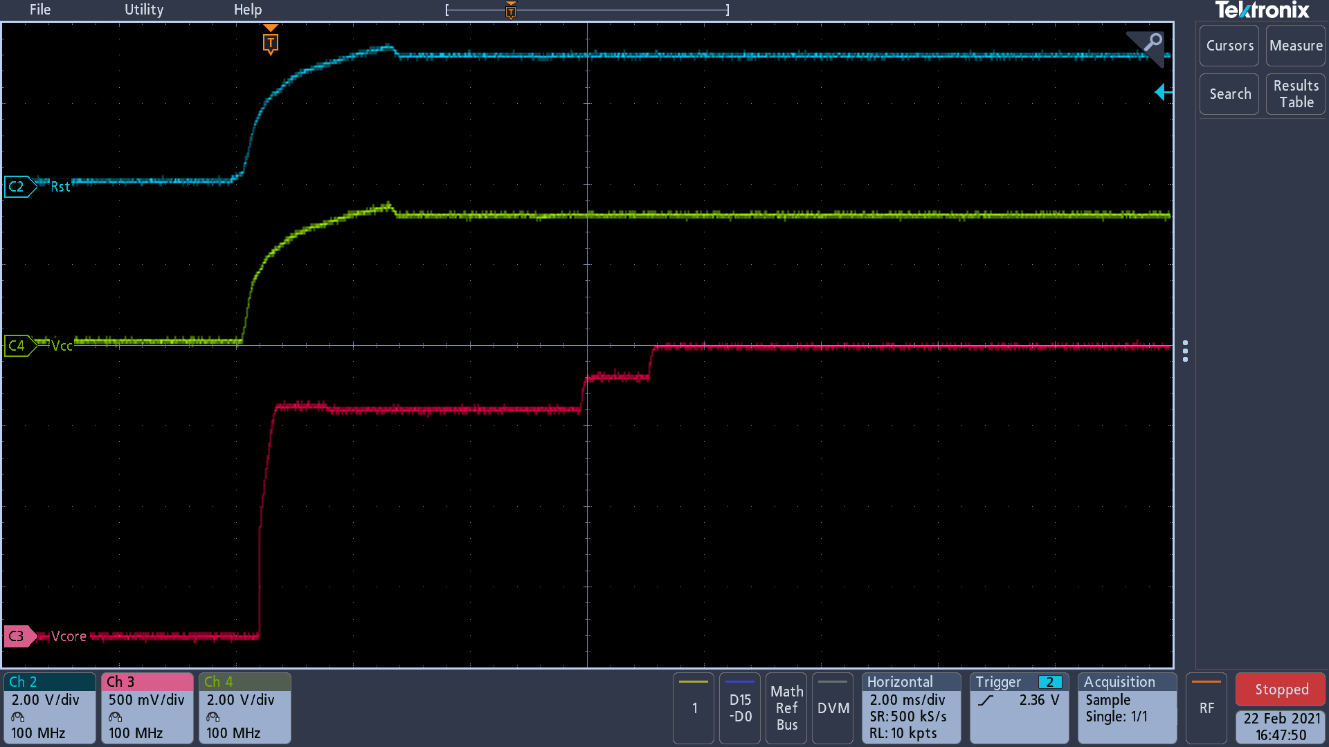
    1) Good_-20C.png is the capture of the unit-A at -20C... this did not have the power up issue.  Note: was good at hot, 25c, -10c etc.

    2) Bad_-30C.png is the capture of the same unit-A at -30C.... it never recovers stays looping waiting for the Vcore to make the last step.  Note: I don't have the timeout in the while(1) loop... so have the original operating system where it loops forever.  However, if I did have the timeout this unit would still not recover.

  • Hi Dave,

    thanks a lot this helps significantly. As you can see in the fail plot Vcore stops at Level 2 and is not increased to Level 3.

    However the Vcore level 2 looks good from voltage point of view. What concerns me a bit is the dip at -20 degC on Vcore level 3.

    Another problem I see at -30 degC picture is that the GND level of DVCC and RST is not GND so do you have something floating here?
    Looks like GND is lifted. Do you have maybe condensates humidity on the board causing leakage paths.
    I think this is the problem why Vcore does not go up and hangs in one of the SVSH IFG check loops because your main supply looks not healthy.

    Interestingly the GND level of Vcore looks ok!

  • We have capacitance that takes some time to bleed off.... The capture that I sent I didn't delay long enough for those supplies to bleed off.

    Here is a capture where I powered off the system, gave it time to bleed off and powered it back on.

  • Dave,

    thanks this looks better but behavior still appears so powering up not from 0V can be excluded as the root cause thanks!

    One more thing the SetVCoreUp function has several while loops where it might go stuck and where you implemented time outs

     line 49 - waiting on SVSMHDLYIFG after enablign SVSMH and SVSHand set new SVSHMHRRL level

     line 71 - waiting on SVSMHDLYIFG after recover old settings if VCC was too low

     line 95 - waiting on SVSMHDLYIFG after SVSHRVL0 to new level

     line 116 - waiting on SVSMHDLYIFGafter enablign SVMLE and SVSLE and set new SVSMLRRL0 + SVSLRVL0 level

    line 152 - waiting on SVSMHDLYIFG and SVSMLDLYIFG

    So because you have a pretty reproducible setup can you please implement port toggles at each stage (1 toggle, 2 toggles 3 toggles,.....) to see at which while(1) it seems to get stuck would be interesting if it is the high or low site delay flag. This would help to look at the exact code location of this function.

    I assume you have checked all the existing PMM ERRATAs on this device which are related to SVSH and SVSL?

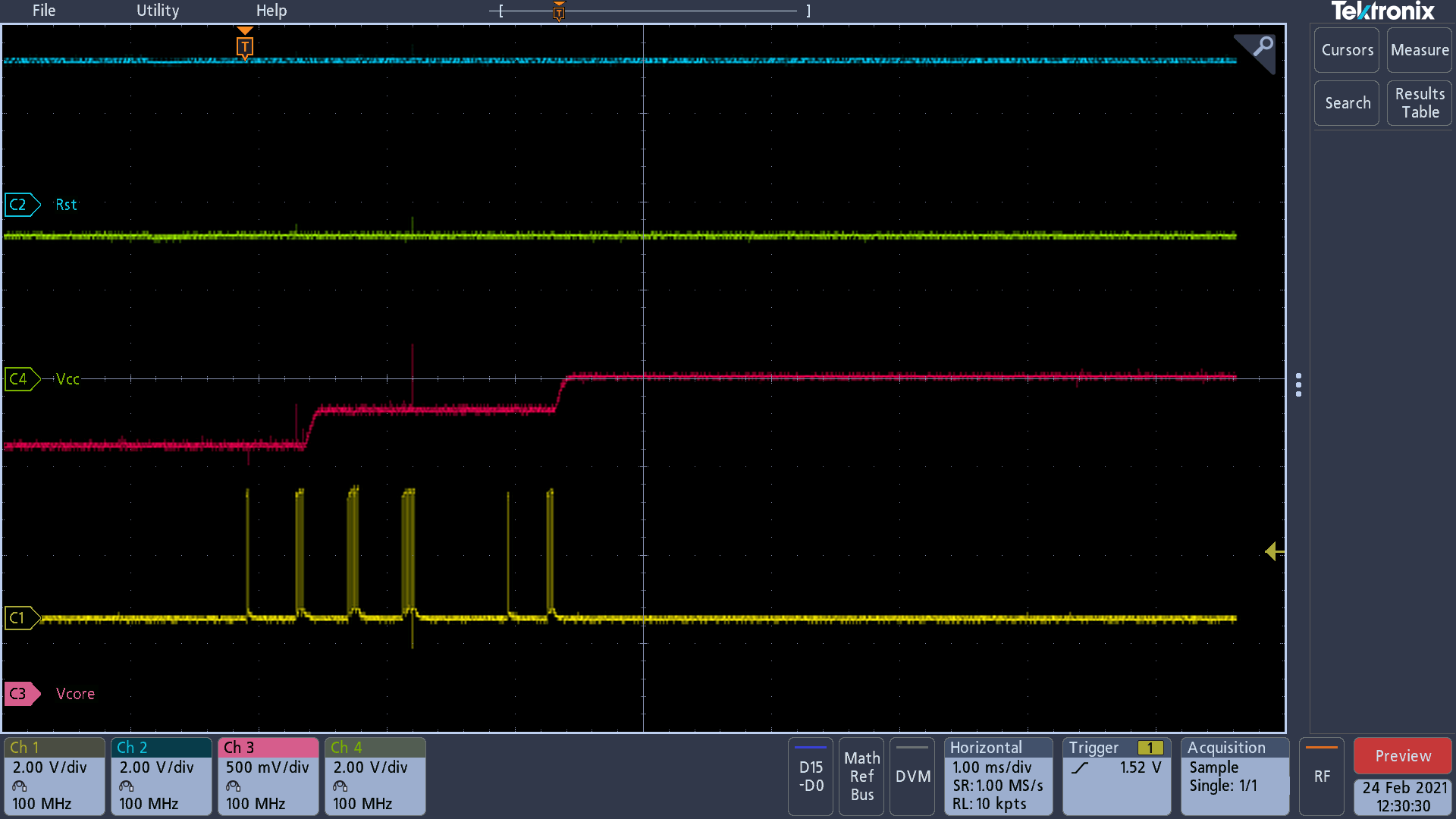
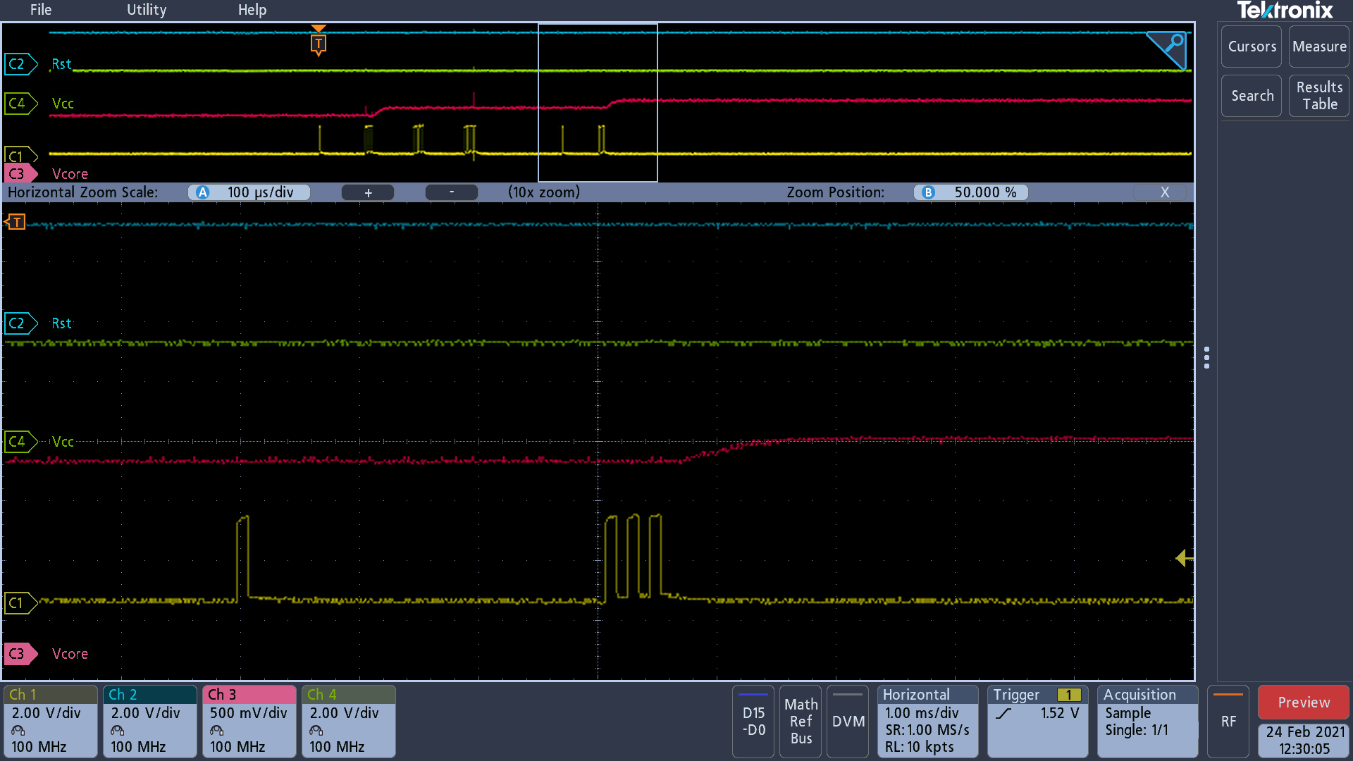
  • I've added the port pulse to identify specifically which while(1) loop we get stuck.  Attached is the capture, looks like it is hanging as we are working on level 2.  Here is the code where it is getting stuck ....  I've attached the capture, the second capture is zoomed in on the failed event.

    // Clear flag
    PMMIFG &= ~SVSMHDLYIFG;

    // Set VCore to new level
    PMMCTL0_L = PMMCOREV0 * level;

    // Set SVM, SVS low side to new level
    SVSMLCTL = SVMLE | (SVSMLRRL0 * level) | SVSLE | (SVSLRVL0 * level);

    // Wait until SVM, SVS low side is settled
    #if 1
    Core_time_counter = 0;
    __delay_cycles(120); // about 5 u seconds
    while ((PMMIFG & SVSMLDLYIFG) == 0) {
    if(Core_time_counter++ > VCORE_LOOP_DELAY) // timeout delay
    WDTCTL = 0; // something not working force a Reset to the RTC system
    }
    /*TESTING BEGIN REMOVE */
    // toggle 4
    P6OUT |= P6_5_RES_GND;
    P6OUT &=~ P6_5_RES_GND; // low
    P6OUT |= P6_5_RES_GND;
    P6OUT &=~ P6_5_RES_GND; // low
    P6OUT |= P6_5_RES_GND;
    P6OUT &=~ P6_5_RES_GND; // low
    P6OUT |= P6_5_RES_GND;
    P6OUT &=~ P6_5_RES_GND; // low
    /*TESTING END */
    #else
    while ((PMMIFG & SVSMLDLYIFG) == 0);
    #endif

  • Dave,

    thanks for the experiment, very helpful. This shows us that the part is hanging in the loop waiting on the SVSML delay to expire but obviously it does not. Because RESET and SUPPLY are stable at this time PMM26 existing on some older F5xx devices can be excluded.

    The delay is implemented to mask voltage settling on the supply voltage supervisors during power mode change or access on SVSMLCTL access as shown in the user guide. The length of the delay depends on performance mode (full is ~12.5 us) and normal is around 100us - 150us. You use the normal mode which is ok to consider PMM14 errata.

    It is also that the device not goes stuck because you time out function works if used which really means to me that the delay flag is not set OR the delay is never triggered. What really wonders me is that the delay works at higher or normal temperature and also at the increase from Vcore 0 to 1.

    This tells me the delay and the trigger circuit should work! I also triple checked the ERRATA and my history but can confirm we never have seen this on any F5xx device.

    Can you please double confirm on how many units (absolute and relative) you can see this behavior?
    So to take the next step can you please provide the disassembly view of the code portion above to review it for any obvious anomalies?

**Attention** This is a public forum