This thread has been locked.

If you have a related question, please click the "Ask a related question" button in the top right corner. The newly created question will be automatically linked to this question.

MSP430FR6043: Problem with transmit data on higher SPI frequency.

Part Number: MSP430FR6043

Hi!


My environment:

MSP430FR6043
Launchpad CC1352R1
CCS: 10.1
MSP SDK: 3.80.10.09
CC SDK: 4.40.04.04

Problem:

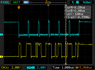
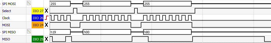
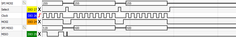
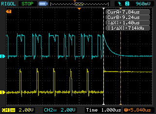
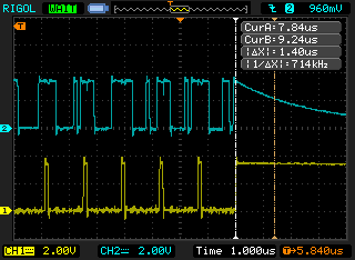
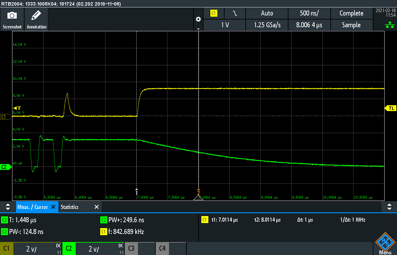
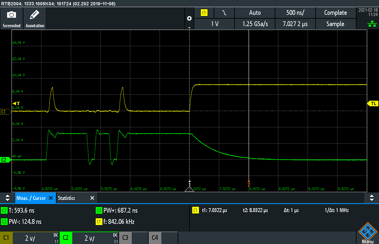
I'm traying to using SPI with DMA on MSP430FR6043 to get higher transmit frequency. MSP is connected to CC1352R1 which is Master. Everything works fine until I set SPI frequency to 1 MHz or higher, transmit data on MSP (MISO) started to be shifted/delayed (something like that). As a result not all data is transmitted and I never get interrupt from DMA.

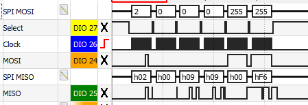
Example setup: SPI is set to 2MHz, DMA transmit and receive channels are set to 6 byte length. Data is 6 byte: 0x2, 0x0, 0x09, 0x0, 0xF6, 0xFF. As you can see SPI transmitted same byte two times.

Here is my SPI and DMA configuration, at beginning I setup everything:

EUSCI_A_SPI_initSlaveParam spiParam = { 0 };
spiParam.msbFirst = EUSCI_A_SPI_MSB_FIRST;
spiParam.clockPhase = EUSCI_A_SPI_PHASE_DATA_CAPTURED_ONFIRST_CHANGED_ON_NEXT;
spiParam.clockPolarity = EUSCI_A_SPI_CLOCKPOLARITY_INACTIVITY_LOW;
spiParam.spiMode = EUSCI_A_SPI_4PIN_UCxSTE_ACTIVE_LOW;
EUSCI_A_SPI_initSlave(EUSCI_A0_BASE, &spiParam);
EUSCI_A_SPI_select4PinFunctionality(EUSCI_A0_BASE, EUSCI_A_SPI_ENABLE_SIGNAL_FOR_4WIRE_SLAVE);

DMA_initParam dmaRxParam = {
        .channelSelect = DMA_CHANNEL_0,
        .transferModeSelect = DMA_TRANSFER_SINGLE,
        .triggerSourceSelect = DMA_TRIGGERSOURCE_14,
        .transferSize = SPI_FRAME_SIZE, // 6
        .transferUnitSelect = DMA_SIZE_SRCBYTE_DSTBYTE,
        .triggerTypeSelect = DMA_TRIGGER_RISINGEDGE
};

DMA_initParam dmaTxParam = {
        .channelSelect = DMA_CHANNEL_1,
        .transferModeSelect = DMA_TRANSFER_SINGLE,
        .triggerSourceSelect = DMA_TRIGGERSOURCE_15,
        .transferSize = SPI_FRAME_SIZE, // 6
        .transferUnitSelect = DMA_SIZE_SRCBYTE_DSTBYTE,
        .triggerTypeSelect = DMA_TRIGGER_RISINGEDGE
};

DMA_init(&dmaRxParam);
DMA_init(&dmaTxParam);

before every transfer I reconfigure settings, transfer size and buffers can be changed during program life:

DMA_setTransferSize(DMA_CHANNEL_0, 6); // for example 6 bytes
DMA_setTransferSize(DMA_CHANNEL_1, 6); // for example 6 bytes

DMA_setSrcAddress(DMA_CHANNEL_0, EUSCI_A_SPI_getReceiveBufferAddress(EUSCI_A0_BASE), DMA_DIRECTION_UNCHANGED);
DMA_setDstAddress(DMA_CHANNEL_0, (uint32_t)&rxFrame.data, DMA_DIRECTION_INCREMENT);

DMA_setSrcAddress(DMA_CHANNEL_1, (uint32_t)&txFrame.data, DMA_DIRECTION_INCREMENT);
DMA_setDstAddress(DMA_CHANNEL_1, EUSCI_A_SPI_getTransmitBufferAddress(EUSCI_A0_BASE), DMA_DIRECTION_UNCHANGED);

EUSCI_A_SPI_enable(EUSCI_A0_BASE);

DMA_clearInterrupt(DMA_CHANNEL_0);
DMA_enableInterrupt(DMA_CHANNEL_0);
DMA_enableTransfers(DMA_CHANNEL_0);
DMA_enableTransfers(DMA_CHANNEL_1);

and after every transfer completion I disable DMA and SPI:

DMA_disableInterrupt(DMA_CHANNEL_0);
DMA_disableTransfers(DMA_CHANNEL_0);
DMA_disableTransfers(DMA_CHANNEL_1);
EUSCI_A_SPI_disable(EUSCI_A0_BASE);

Is there something that I missed or configured wrong? Until I'm not set frequency to something like 1MHz and higher everything seems to works like a charm, but I want to use at least 4MHz.

  • How fast is MCLK set to?

    What I see in the trace is that the shifting is byte-wise (bit-wise would be a different symptom), indicating overrun/underrun. That suggests that the DMA can't keep up.

    The DMA only needs 2x MCLKs for a transfer, but there's also "dead time" in the cycle while the clocks synchronize [Ref User Guide (SLAU367P) Sec 11.2.7]. If the FR6043 is in LPM, there may be a further delay while the DCO starts up. And then you have to multiply by 2x for the two directions.

    Is each transaction intrinsically 2-way? I suspect that if you turn off the DMA in one direction (let the unused side just overrun/underrun) you'll gain something.

  • Hi Bruce,

    I am working with Robert on the same project.

    Bruce McKenney47378 said:
    How fast is MCLK set to?


    MCLK is set to 8MHz.

    // Set DCO frequency to default 16MHz
    CS_setDCOFreq(CS_DCORSEL_1, CS_DCOFSEL_4);
    // Set divder to 2
    CS_initClockSignal(CS_MCLK, CS_DCOCLK_SELECT, CS_CLOCK_DIVIDER_2);

    Bruce McKenney47378 said:
    That suggests that the DMA can't keep up.


    It was my point exactly, but the whole picture doesn't stack up.

    Let's count.
    SPI CLK: 2MHz
    SPI word: 8bits
    Spi slave has two shift registers and two latched buffers (UCxRXBUF, UCxTXBUF). According to TRM:
    "
    Data on UCxSIMO is shifted into the receive shift register on the opposite edge of UCxCLK and moved to UCxRXBUF when the set number of bits are received. When data is moved from the RX shift register to UCxRXBUF, the UCRXIFG interrupt flag is set, indicating that data has been received.
    "

    Therefore, an interrupt for DMA is triggered (2MHz / 8bits) with 250kHz frequency.
    According to this, DMA has (1/250kHz) 4us to pick up data.

    It's much more time than DMA requires.
    According to TRM "Table 11-3. Maximum Single-Transfer DMA Cycle Time", DMA requires 4 MCLK cycles (in acctive mode).
    Let's assume the DMA requires 8 MCLK cycles (2-way), we still have 4 times more than required.

    Do we miss something?
    Where is the point?

    Reading Table 11-3 only one answer comes up, we somehow go down to LPM3 (or LPM4), and we require that additional 5us to start DCOCLK. Unfortunately, we believe that we are not going to LPM during SPI transfer.
    Do you have any idea, how to investigate this?

    Regards
    Adam

  • I don't have your equipment, so I tried to construct your test case using an FR6989 as slave, which I suppose has the same eUSCI and DMA as the FR6043. I used an FR5994 as master. In my test case, the DMA was able to keep up at SCK=8MHz.

    One difference I encountered was with the TXIFG. Calling EUSCI_A_SPI_enable sets TXIFG high, so there's no edge to trigger the DMA when the channel is (later) enabled; the symptom was that my Tx side never sent anything. I switched to DMA_TRIGGER_HIGH (DMALEVEL=1) which provided proper operation. I'm not quite sure why you didn't encounter this, the suggestion being that there's some relevant code outside what you posted.

    I'm not sure what we're doing differently. If it's something specific to the FR6043 I won't be much help.

    This is a trace of STE and MISO (0x81-0x86) at 8MHz. I had to insert (at the master) deliberate 3-SCK gaps to make STE wiggle. Even withwithout the gaps it operated properly.

    This is the slave-side program I used:

    /cfs-file/__key/communityserver-discussions-components-files/166/Galon_2D00_s_2D00_6989.c

  • Hi Bruce,

    Your information is very helpful.
    You put so much effort to reproduce our case. We appreciate it. Thank you.

    On Monday, we will follow your suggestions and keep you informed.

    Regards
    Adam


  • Hi Bruce.

    Finally we make it works. There were two things that I had to fix: change DMA TX trigger to DMA_TRIGGER_HIGH as you said (I have no idea why it works on DMA_TRIGGER_RISINGEDGE with lower frequency), and make device stay in LPM0 for transaction time. After these two changes SPI with DMA is working nice on 8MHz frequency.


    I'm still wondering about two things:

    1. In my code I first initialize SPI and later enable DMA transfers. Is it okay this way or should I do it vice versa? Which way is better?

    2. Now I have something weird on MISO pin, it's like SPI's transmitting one byte more than I set. I double checked parameters and everything looks fine, so I have no idea what can cause it.

  • 1) I think you could do either, you just need to keep track of what TXIFG is doing. You do want to make sure TXBUF is pre-loaded, since once the first SCK appears there will be no time for the DMA to run. There are some hazards with using DMALEVEL=1 [Ref UG (SLAU367P) Sec 11.2.3.2], but with what you're doing I don't think you'll encounter any of them.

    2) The SPI (slave) unit will send as many bytes as the master (SCK) requests, regardless of how many are loaded into TXBUF by the DMA. I would expect this to show up as repetitions of the final byte, which isn't what I see here. Are you still using DMA_TRANSFER_SINGLE? (I didn't try this case.)

    [Edit: I forgot to ask: Is your code writing directly to TXBUF anywhere? (EUSCI_A_SPI_transmitData)]

  • 2)

    I think Robert misinterpreted this last edge on MISO.
    To eliminate possible leakage current, after completing the SPI transaction, we pull down the Master's inputs (internal pulldown resistor).

    What we see is probably the following sequence:

    • last byte
    • MISO goes Hi-Z or High (Slave). I'm not sure how this is defined on the Slave side.
    • Master pulls down MISO (SPI transaction finished)

    Tomorrow, we will double-check it and let you know if it is the issue.

    BTW. Similar behavior we see on the original waveform (e2e.ti.com/.../spi-msp-dma.png), but the CLK is much lower. 

    Regards

    Adam

  • 1) Thank you for pointing to manual, it's really helpful to understand.

    2) Yes, I'm still using DMA_TRANSFER_SINGLE.

    I make some more tests and I found out some correlative behavior between MOSI state and last byte. When first bit of last byte starts with high bit (e.g. 0x80) there is this high MOSI state after transaction:

    but when last byte starts with low bit (0x00) there is nothing added:

    Also I setup MISO pin as Input Pull Up from Master side when SPI is not used, but this occur more than 80us after what we're seeing here, so it's to be something on MSP side.

    I forgot to ask: Is your code writing directly to TXBUF anywhere? (EUSCI_A_SPI_transmitData)

    I tried once to set first byte manually before transaction (just written to TXBUF), but this didn't help. Now I don't have anything like that, only DMA is writing to SPI registers.

  • MISO is supposed to go Hi-Z after STE is de-asserted [Ref UG Sec 31.3.4.1] I wouldn't be too surprised if it floated at its final level for a little while.

    Do you suspect it's actually being driven after STE is de-asserted? 

  • Hi Bruce,

    Bruce McKenney47378 said:
    Do you suspect it's actually being driven after STE is de-asserted?

    We did more experiments to ensure who drive the line after the last byte is sent. We attached the additional 33k resistor, which permanently pulls down MISO.
    Even with this resistor attached, we see this additional high level after the last byte is sent.

    The sequence is as follows (see the picture attached):

    • the last byte sent
    • CS released
    • the MISO line stays for about 1.4us in the high state. The line is driven high by MSP (slave), which proves the experiment with this additional pull-down resistor.
    • 80us later, Master changes the MISO PIN configuration to the default state. In our case master attaches an internal pull-down resistor and keeps it as an input (to avoid leakage current).


    It's not essential for us to solve this mystery, but it would be nice to know why does it happen so.
    Any idea?

    Regards
    Adam

  • I suppose that would be tSTE,DIS, rated at 50ns (max), which is, um, different from 1400ns. [Ref data sheet (SLASEF5A) Sec 8.13.8.6; it looks like they re-numbered all the sections for doc rev A]. I don't know what to suggest (no one gave me the keys to the Verilog).

    A couple of shots-in-the-dark:

    1) Are you by chance using an "X" device (pin marking "XMS430" rather than "MSP430")? Launchpads often come with "X" devices, but I don't know about EVMs. "X" devices sometimes have quirks in the corners, that are fixed by the time they become "M" devices.

    2) Are you using the REN resistor on the MISO pin? I know, e.g. that the eUSCI in I2C mode doesn't disable the REN resistor, maybe that's also true in SPI mode.

  • I forgot to mention that the length of this "high" state is not equal to the length of the SPI word (byte).
    It looks similar in this particular picture, and only at this SCLK.
    If we lower the frequency, the SPI word will be longer than this unintended "high" state.

  • 1) We are using our custom board with MSP430. The chip was bought in the original TI store and not marked as obsolete or under development.

  • Bruce McKenney47378 said:
    2) Are you using the REN resistor on the MISO pin?


    I don't think so, but I'll double-check it tomorrow.
    We carefully measure the current, and we stay more or less at 1.5uA during the device inactivity. I wouldn't believe it's possible with either pull-up or pull-down attached in an unintended way.

  • I tried two test cases on the setup I had been using (FR5994 master, FR6989 slave). The cursors are 1.4us apart.

    (1) a 4.7k external pulldown 

    (b) internal pulldown (~20k)

    It's no surprise that the 20k is slower, but I don't see any real evidence that the slave is driving after STE.

    Of course, the FR6989 is a different (sibling) chip, but is it possible your analyzer is being over-liberal?

  • Hi Bruce.

    You are absolutely right, what we actually see is a discharging of the RC circuit.

    Confirmation:
    When we connect an external smaller pull-down resistor 4.7k, the "high" state gets shorter (300ns).

    When we connect an oscilloscope, we see the RC discharging curve.

    Thank you for your assistance and the effort you put to help solve our problems. See you next time.
    Below I enclose waveforms from the oscilloscope with different values of an external pull-down resistor for any reader seeking confirmation.

    Without an additional pull-down resistor, with 33k resistor and with 4.7k resistor.


    Regards
    Adam


**Attention** This is a public forum