This thread has been locked.

If you have a related question, please click the "Ask a related question" button in the top right corner. The newly created question will be automatically linked to this question.

MSP430F5528: Timer Inputs

Part Number: MSP430F5528

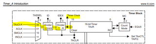
The data sheet seems to suggest that an external signal input to a timer module can be as high as the system frequency.

If the device operates at 25MHz, can the timer support up to 25MHz input signals, and still increment the counter every rising edge? This is assuming 50% duty cycle.

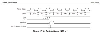
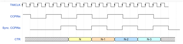
some devices like the CC26x0 suggest the need for one or two system clock periods to lock in the rising edge and update the count register...

Does this device update the count register on the rising edge of the first system clock after an edge was detected?

if so, how much time is needed from a signal falling edge, before the next rising edge can be detected and locked into the count register?

  • Hello Darren,

    I guess you don't mean inputting a Timer Clock, but actually trying to measure a 25MHz PWM input into the timer in capture mode?  How do you expect it to work exactly?  A few 1 count pulses detected? 

    Instead of system clock, everything in the timer should be driven by the Timer Clock, although they may be the same speed or clock source. 

    Based on Figure 12-10 of the User's Guide, the Capture is recognized on the falling edge of the Timer clock.  

    For your last question, The datasheet says both Timer_A and Timer_B the absolute fastest pulse that could be detected on the Timer capture is 20ns, so it should be able to detect a 25MHz pulse.    

    Even then, It's going to take longer than the pulse to actually service the interrupt and read the timer registers, so I'm not sure what the use case here would be exactly.  

    Thanks,

    JD


  • Hi JD, 

    EDIT: I don't understand how capture mode would be used...you have to read the timer value after a capture event, or else "...if a second capture was performed before the value from the first capture was read...COV is set"

    I am not talking about capturing a single pulse. I meant using the timer inputs for event capturing. Basically, you set the TCA0CLK input to an external pin, then apply a signal to this pin. 

    From the TRM:

    The 16-bit timer/counter register, TAxR, increments or decrements (depending on mode of operation) with each rising edge of the clock signal.

    I am talking about using an external signal as the "clock signal" - so that the TAxR increments/decrements each time there is a rising edge from this external signal.

    My understanding is this is doable, but not at 25MHz. The main reason is the system clock is running at 25MHz, but to lock in the detected edge and update the TAxR register, takes 2 system-clock (25MHz) cycles.

    I made an example, and attached the image. Here, TIMCLK would be the system-clock (25MHz)
    Then, CCPINx would be the actual signal input to TA0CLK pin.
    Then, after two TIMCLK rising edges after CCPINx goes high, this gets locked in, and on the next rising edge of TIMCLK, TAxR gets updated. This effectively limits the 25MHz to 25MHz / 4 = 6.25MHz, right?

  • Data sheet (SLAS590N) Sec 5.27 claims that TA can accept a 25MHz TACLK, so I take it at its word. If one imagines the timer peripheral itself running from TACLK, it seems plausible. The various UG notes about "clocked asynchronously" would presumably apply.

  • Hey Darren,

    I still don't fully grasp what you are trying to do, but I'm starting to follow.  

    First seems to be using an external signal as the Timer Clock source.  This would be done with the TAxCLK pin on the MCU.  As Bruce Mentioned, the Datasheet states that external TAxCLK can be up to 25MHz. 

    This clock can be fed in without a divider, and will be the Timer Clock.    

    TAR will increment/decrement on every rising edge of the Timer Clock.  

    It sounds like we agree up to this point, and I expect the input signal to work up to 25MHz.  I don't understand what your concern is beyond this point. 

    Where are you seeing system clock gating TAR incrementing?

    Thanks,

    JD  

  • Hi JD, 

    I figured out what I was getting wrong.

    1) Originally I assumed any MCU that said it can accept external inputs for the Timer, would update the counter with this signal
    2) Then I learned for the CC26x0 devices, they "can't" do this - they use a "master" clock to "clock-in" the edge
    For the SBD, see p1190 of https://www.ti.com/lit/ug/swcu117i/swcu117i.pdf - there is a "PERDMACLK" that goes to "Edge-Detect" block
    Then, there is the NOTE on p1193

    This was confusing me.
    I understand now that a device may state it has external input to the Timer Clock, but it doesn't necessarily mean the count value is updated directly on that external clock.
    Some devices directly use the external clock to update the timer count (MSP430F5528) while other devices use a master clock to synchronize (noise-immunity?) the edge and shift the detection into the timer counter (CC26x0)

    I get it know.

    Thanks!

    Darren

  • Just to see, I hacked up a copy of msp430f55xx_ucs_10.c to run TA1 from TA1CLK (P1.6)  with OUTMOD=4 and CCR0=25000/2 to TA1.0 (P1.7) . When I patched SMCLK (P2.2) to TA1CLK, I got a very steady 1kHz square wave on TA1.0. 

    So I think it actually works.

**Attention** This is a public forum