Hello Team,
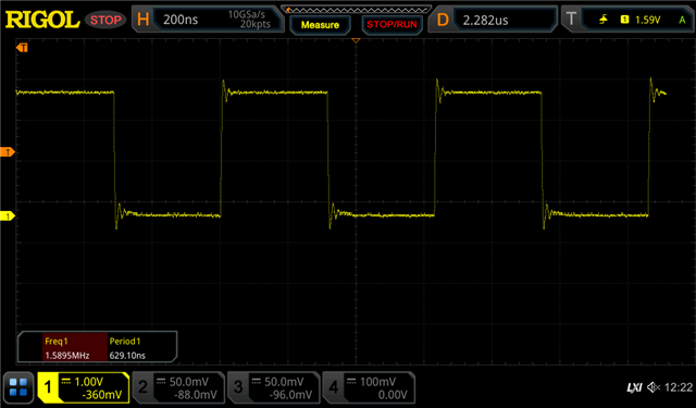
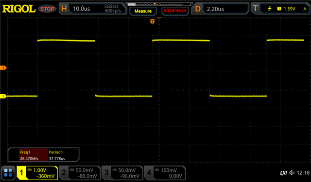
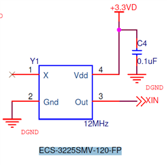
We are working on our custom board to generate 24Mhz from external 12Mhz crystal we observing strange behavior of clock source. When we toggle LED in while loop we are getting period 806 nano seconds(this is calculated based on toggle cycles(16 * 1/assuming 20Mhz clk)). may be we get strucked in configuration. Can anyone please look into configuration we have done and may be we mistaken in configuration. Please any help would be very thankful.
int main(void)
{
    WDTCTL = WDTPW | WDTHOLD;   // stop 'Watch-dog' timer
    // Watch-dog will be configured for >10ms and enabled!

    Init_Sys_Clock();   // initialize System Clocks
    Init_GPIOs();       // initialize GPIOs

     while (1)
    {
         P6OUT ^= BIT6;
    }
}

void Init_Sys_Clock(void)
{
    // Setting clock to 24Mhz
    P2SEL1 |= BIT7;          // P2.7: crystal pins

    __bis_SR_register(SCG0);        // disable FLL
    CSCTL1 = DCORSEL_7;             // Set DCO = 24MHz
    CSCTL2 = FLLD_0 + 1;          // DCOCLKDIV = 24MHz

    __delay_cycles(3);
    __bic_SR_register(SCG0);        // enable FLL

     CSCTL4 = SELMS__XT1CLK | SELA__XT1CLK; // set XT1 (12Mhz) as ACLK source
                                            // default DCOCLKDIV as MCLK and SMCLK source
     CSCTL6 = XT1BYPASS_1 | XTS_1 | DIVA_8 | XT1HFFREQ_2 | XT1AGCOFF_1 | XT1DRIVE_3;

}