This thread has been locked.

If you have a related question, please click the "Ask a related question" button in the top right corner. The newly created question will be automatically linked to this question.

MSP430F2618: I2C - unexpected behavior of the USCI

Part Number: MSP430F2618
Other Parts Discussed in Thread: MSP430F2619

During an EMC test, we noticed the following:

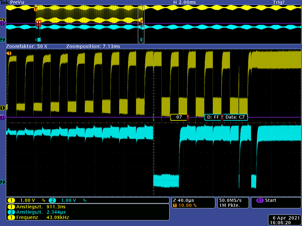
(ref to the enclosed  image)

  • Transmissions are aborted at the first 1-bit. We assume that the USCI detects an arbitration lost error at this point because the incoming RF distorts the signal.
  • Why does the USCI continue to generate CLK clocks? Is there anything we can do to prevent this?
  • Before the second transmission starts, the USCI is reset and reinitialized by software. The clock runs until this software-initiated reset. Why does it run until here?
  • According to the Family Users Guide the UCALIFG will be set if the USCI detects an arbitration lost error. When UCALIFG is set the UCMST bit is cleared and the I2C controller becomes a slave. But after the UCMST is cleared the USCI should not generate any clock!!!  (We operate all in single master mode and slave doesn't generate any clocks!)

Oscillogram 1

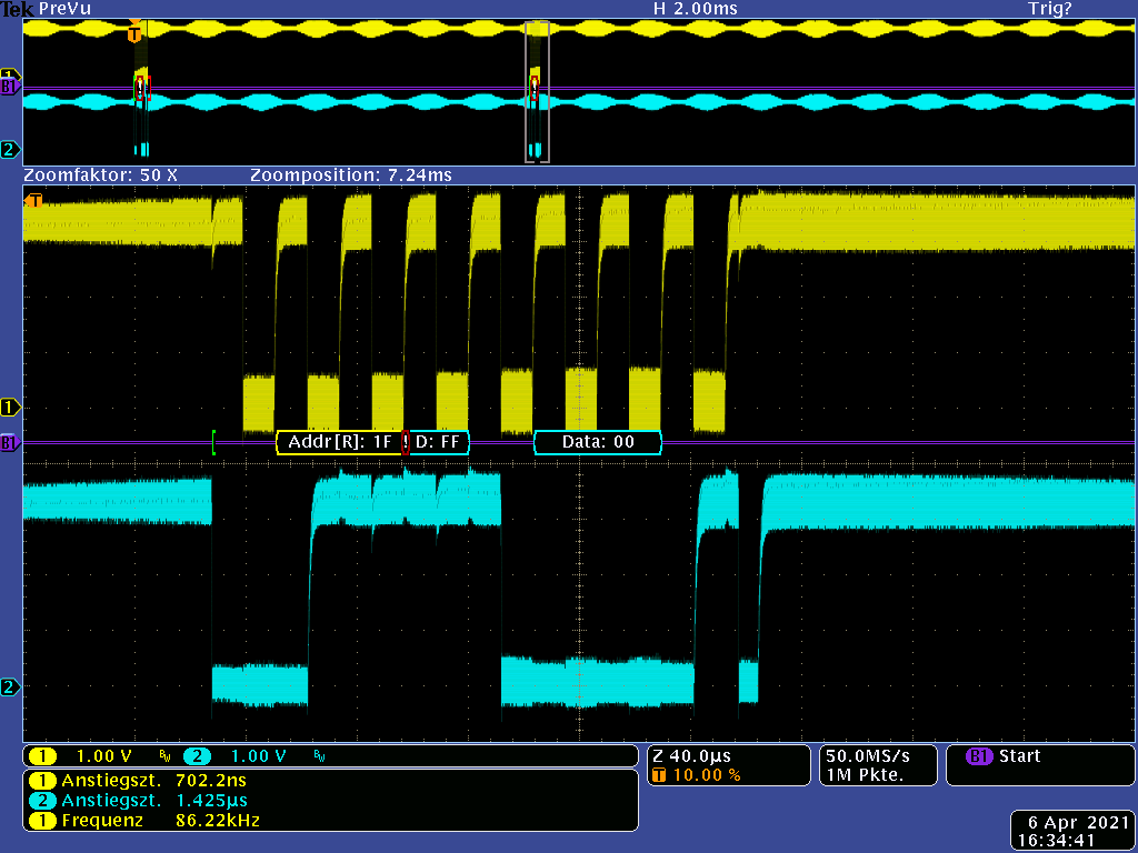
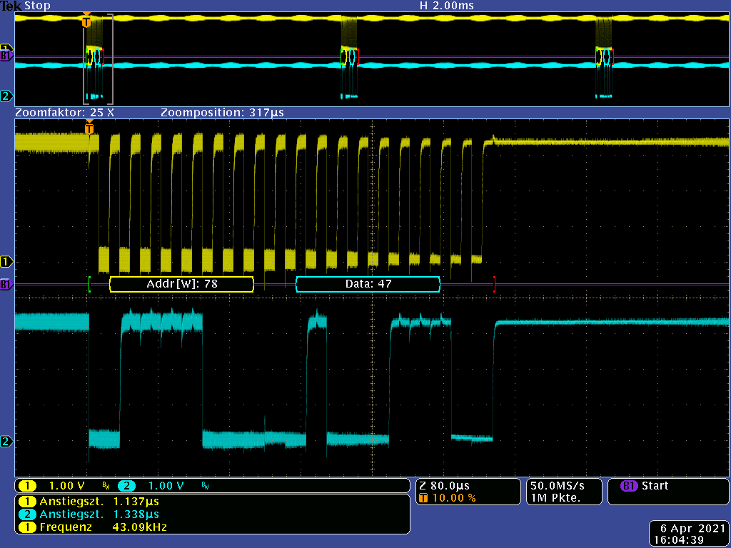
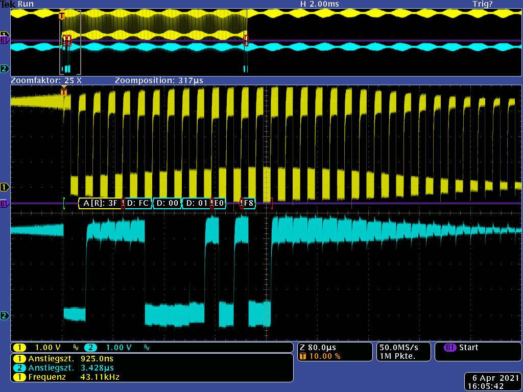
In addition, we also observed (next image) that the clocking continued even though the RF exposure had ended.

  • SDA is permanently high. About 20 clocks can be seen. These must come from the USCI!
  • Why does the USCI not stop? Because after 8 clocks and a NACK, the USCI should keep its feet still.
  • How can the USCI get into this state?

Oscillogram 2

We look forward to your response.

Thanks.

<<<<<<<<<<<<<<<<<<<<<<<<<< END OF THE FIRST POST  >>>>>>>>>>>>>>>>>>>>>>>>>>>>>

Add on for the 3rd Post:

  • Hi Peter,

    You use F2618 in I2C mater mode, right? Could you share some code?

    Thanks!

    Best Regards

    Johnson

  • Hi Johnson,

    in our code we strictly followed the code from the TI Application Report slaa382A Using the USCI I2C Master (get it from your website https://www.ti.com/lit/pdf/slaa382).

    We are using the USCI in combination with the DMA.

    Therefore a call for a transmission looks like this:


          if(!(*((*PtrRead).Ptr_BytesToSend) & 0x01)) // Tx
          {
            TI_USCI_I2C_DMA_transmitinit(set_address(), I2C_prescale);
            TI_USCI_I2C_DMA_transmit((*PtrRead).No_DataBytes,(*PtrRead).Ptr_BytesToSend+1);
          }
          else  // Rx
          {
            TI_USCI_I2C_DMA_receiveinit(set_address(), I2C_prescale);
            TI_USCI_I2C_DMA_receive((*PtrRead).No_DataBytes,(*PtrRead).Ptr_MemToStoreTo);
          }
    

    We actually use the TI_USCI_I2C_master_dma.c and .h from the Application Report, coded by TI's best programmers Uli Kretzschmar and Christian Hernitscheck.

    Is that enough of a code example?

  • Hello Johnson,
    we continued to research the problem.
    We were unable to confirm our suspicion that the observed USCI misconduct was related to an Arbitration Lost.

    To rule out a bug in our software, we built a simple test software, which basically consists of the original code example from the Application Report SLAA382.
    We have only programmed a small loop in the main() to continuously have frames on the bus and made provisions to detect an arbitration lost.

    To be clear: we have only (almost) original TI software (with DMA) and the MSP430 without a slave on the bus and get to see the following:

    refer to the 3rd image in the 1st post   (insertion of an image not working in reply mode Unamused)

    Please follow these explanations about the image:
    - The loop sends a frame to addr 0x78 every ~32ms.
    - Since no slave is present, the addr is not acknowledged.
    - The StopCondition is also correct.
    - But here sometimes the USCI starts to send clocks independently until the next frame is sent by the software.

    Yes, we interfere with the MSP with a small EMC interference radiation. But in doing so it is unlikely to cause a level violation. Nevertheless, it does not explain that the USCI sends clocks permanently for no reason.
    How can this be prevented???

    We have a big problem with this behavior of the USCI.
    Because if the error occurs during a transfer to an external memory, we have observed that the complete content is overwritten with 0xFF!

    Here is the complete code:

    /*** USCI master library with DMA **********************************************
    
    In this file the usage of the USCI I2C master library with DMA support is shown. 
    This library uses pointers to specify what data is to be sent. The usage of the 
    DMA is transparent to the user.
    
    When calling the TI_USCI_I2C_DMA_receive or TI_USCI_I2C_DMA_transmit routines 
    the number of bytes, which are to be transmitted or received have to be passed  
    as well as a pointer to a data field, that contains(or stores) the data.
    
    This code checks if there is a slave with address 0x50 is connected to the I2C
    bus and if the slave device is present, bytes are received and transmitted.
    
    Uli Kretzschmar
    MSP430 Systems
    Freising
    *******************************************************************************/
    #include "msp430x26x.h"
    #include "TI_USCI_I2C_master_dma.h"
    
    typedef unsigned char  u8;
    typedef  unsigned int u16;
    
    __no_init volatile struct
                       {
                         u8 MOD:5;                  //!< DCO: Modulator selection
                         u8 DCO:3;                  //!< DCO: Frequency selection
                       }DCOCTL_Reg @ DCOCTL_;       //!< Bitfield zur Einstellung der DCO-Frequenz
    __no_init volatile struct
                       {
                         u8 RSEL   :4;              //!< DCO: Range Selection
                         u8 DIVA   :2;              //!< DCO: Divider for ACLK
                         u8 XTS_1  :1;              //!< DCO: LFXT1 mode select
                         u8 XT2_OFF:1;              //!< DCO: XT2 off
                       }BCSCTL1_Reg @ BCSCTL1_;     //!< Bitfield zur Einstellung der DCO-Frequenz
    
    #define RSEL_Value 11                           //!< DCO setzen [3,00MHz...5,50MHz], DCO_11_3
    #define DCO_Value  3                            //!< DCO setzen [3,00MHz...5,50MHz], DCO_11_3
    #define MOD_Value  15                           //!< DCO setzen [3,00MHz...5,50MHz], DCO_11_3
    const u16 I2C_prescale = 88;     //!< Teiler für die Taktrate bei I2C, 4,13 MHz / 88 = 46,9 kHz
    
    unsigned char array[40] = { 0x00, 0x02, 0x3, 0x4, 0x5, 0x6, 0x7, 0x8, 0x9, 0xa, 0xb };
    
    #define I2C_Slave_Adr_LCD 0x78 >> 1
    
    void main(void)
    {
      WDTCTL = WDTPW + WDTHOLD;                 // Stop WDT
    
      BCSCTL1_Reg.RSEL = RSEL_Value;     // DCO aus 4,13 MHz einstellen
      DCOCTL_Reg.DCO = DCO_Value;        // DCO aus 4,13 MHz einstellen
      DCOCTL_Reg.MOD = MOD_Value;        // DCO aus 4,13 MHz einstellen
    
      _EINT();
    
      TI_USCI_I2C_DMA_transmitinit(I2C_Slave_Adr_LCD,I2C_prescale);// init transmitting with USCI and DMA
      do
      {
        TI_USCI_I2C_DMA_transmitinit(I2C_Slave_Adr_LCD,I2C_prescale);// init transmitting with USCI and DMA
        TI_USCI_I2C_DMA_transmit(2,array);       // start transmitting with DMA
        
        for(u16 i=0; i < 10000; i++)        // waste time ~32ms
        {
          _NOP();
        }
      }
      while(1);
    }


    //******************************************************************************
    //   MSP430 USCI I2C Transmitter and Receiver with DMA support
    //
    //  Description: This code configures the MSP430's USCI module as 
    //  I2C master capable of transmitting and receiving bytes. DMA is used for
    //  transmitting and receiving of data.
    //
    //  ***THIS IS THE MASTER CODE***
    //
    //                    Master                   
    //                 MSP430F2619             
    //             -----------------          
    //         /|\|              XIN|-   
    //          | |                 |     
    //          --|RST          XOUT|-    
    //            |                 |        
    //            |                 |        
    //            |                 |       
    //            |         SDA/P3.1|------->
    //            |         SCL/P3.2|------->
    //
    // Note: External pull-ups are needed for SDA & SCL
    //
    // Uli Kretzschmar
    // Texas Instruments Deutschland GmbH
    // November 2007
    // Built with IAR Embedded Workbench Version: 3.42A
    //******************************************************************************
    #include "msp430x26x.h"                        // device specific header
    #include "TI_USCI_I2C_master_dma.h"
    
    unsigned char byteCtr;
    unsigned char last;
    unsigned char *save;
    
    //------------------------------------------------------------------------------
    // void TI_USCI_I2C_DMA_transmitinit(unsigned char slave_address, 
    //                                   unsigned char prescale)
    //
    // This function initializes the USCI module for master-transmit operation. 
    //
    // IN:   unsigned char slave_address   =>  Slave Address
    //       unsigned char prescale        =>  SCL clock adjustment 
    //------------------------------------------------------------------------------
    void TI_USCI_I2C_DMA_transmitinit( unsigned char slave_address, 
                                       unsigned char prescale)
    {
      // USCI module initialization
      P3SEL |= SDA_PIN + SCL_PIN;                 // Assign I2C pins to USCI_B0
      UCB0CTL1 = UCSWRST;                        // Enable SW reset
      UCB0CTL0 = UCMST + UCMODE_3 + UCSYNC;       // I2C Master, synchronous mode
      UCB0CTL1 = UCSSEL_2 + UCSWRST;              // Use SMCLK, keep SW reset
      UCB0BR0 = prescale;                         // set prescaler
      UCB0BR1 = 0;
      UCB0I2CSA = slave_address;                  // Set slave address
      UCB0I2CIE = UCNACKIE + UCALIE;
      UCB0CTL1 &= ~UCSWRST;                       // Clear SW reset,resume operation
    
      // DMA initialization
      DMA0CTL &= 0;                               // disable DMA channel 0
      DMACTL0 = DMA0TSEL_13;                      // select UCB0RXIFG is dma trigger
      DMA0CTL |= DMASRCINCR_3;                    // incremet source addr after dma
      DMA0CTL |= (DMADSTBYTE + DMASRCBYTE);       // byte to byte transfer
      DMA0CTL |= DMAIE;                           // enable dma interrupt
      DMA0DA = (unsigned short) &UCB0TXBUF;        // set DMA dest address register
    
    }
    
    //------------------------------------------------------------------------------
    // void TI_USCI_I2C_DMA_transmit(unsigned char byteCount, unsigned char *field)
    //
    // This function is used to start an I2C commuincation in master-transmit mode. 
    //
    // IN:   unsigned char byteCount  =>  number of bytes that should be transmitted
    //       unsigned char *field     =>  array variable. Its content will be sent.
    //------------------------------------------------------------------------------
    void TI_USCI_I2C_DMA_transmit(unsigned char byteCount, unsigned char *field){
      DMA0SA = (unsigned long) field;             // set DMA src address register  
      DMA0SZ = byteCount ;                    // block size 
      DMA0CTL |= DMAEN;                           // enable DMA channel 0  
      
      UCB0CTL1 |= UCTR + UCTXSTT;                 // I2C TX, start condition
    }
    
    #pragma vector = USCIAB0RX_VECTOR
    __interrupt void USCIAB0RX_ISR(void)
    {
      if (UCB0STAT & UCNACKIFG){            // send STOP if slave sends NACK
        UCB0CTL1 |= UCTXSTP;
        UCB0STAT &= ~UCNACKIFG;
      }
    
      if (UCB0STAT & UCALIFG){
        while(1);
      }
    }
    
    #pragma vector = USCIAB0TX_VECTOR
    __interrupt void USCIAB0TX_ISR(void)
    {
      if ((IFG2 & UCB0RXIFG) && (DMA0CTL & DMAIE))	// RX
      {
        if (last == 2)
        {
          UCB0CTL1 |= UCTXSTP;
          save[byteCtr-2] = UCB0RXBUF;
          last--;
        }
        else
        {
          save[byteCtr-1] = UCB0RXBUF;
          IFG2 &= ~UCB0RXIFG;
          IE2 &= UCB0RXIE;
        }
      }
      else											// TX immer mit DMA
      {
        UCB0CTL1 |= UCTXSTP;
        IFG2 &= ~UCB0TXIFG;
        IE2 &= UCB0TXIE;
      }
    
    }
    
    // DMA interrupt service routine
    #pragma vector=DMA_VECTOR
    __interrupt void dma (void)
    { 
      DMA0CTL &= ~DMAIFG;
      if (UCB0CTL1 & UCTR)            // wait til next TX-int to send stop condition
        IE2 |= UCB0TXIE;
      else 
      {
        IE2 |= UCB0RXIE;                      // enable RX int to receive last 
      }
    }


    /*** USCI master library with DMA **********************************************
    
    Uli Kretzschmar
    MSP430 Systems
    Freising
    *******************************************************************************/
    #ifndef USCI_LIB
    #define USCI_LIB
    
    #define SDA_PIN 0x02                                  // msp430x261x UCB0SDA pin
    #define SCL_PIN 0x04                                  // msp430x261x UCB0SCL pin
    
    void TI_USCI_I2C_DMA_transmitinit( unsigned char slave_address, 
                                   unsigned char prescale);
    
    void TI_USCI_I2C_DMA_transmit(unsigned char byteCount, unsigned char *field);
    
    #endif
    

    Additional note: We tried the code sample from the Application Report both - with and without DMA - and got the same result.

  • hI Peter,

    I did some test in my side using MSP430F2619(this is same with F2618), and I don't find any abnormal for SCL.

    Attach my test code:

    /* --COPYRIGHT--,BSD_EX
     * Copyright (c) 2012, Texas Instruments Incorporated
     * All rights reserved.
     *
     * Redistribution and use in source and binary forms, with or without
     * modification, are permitted provided that the following conditions
     * are met:
     *
     * *  Redistributions of source code must retain the above copyright
     *    notice, this list of conditions and the following disclaimer.
     *
     * *  Redistributions in binary form must reproduce the above copyright
     *    notice, this list of conditions and the following disclaimer in the
     *    documentation and/or other materials provided with the distribution.
     *
     * *  Neither the name of Texas Instruments Incorporated nor the names of
     *    its contributors may be used to endorse or promote products derived
     *    from this software without specific prior written permission.
     *
     * THIS SOFTWARE IS PROVIDED BY THE COPYRIGHT HOLDERS AND CONTRIBUTORS "AS IS"
     * AND ANY EXPRESS OR IMPLIED WARRANTIES, INCLUDING, BUT NOT LIMITED TO,
     * THE IMPLIED WARRANTIES OF MERCHANTABILITY AND FITNESS FOR A PARTICULAR
     * PURPOSE ARE DISCLAIMED. IN NO EVENT SHALL THE COPYRIGHT OWNER OR
     * CONTRIBUTORS BE LIABLE FOR ANY DIRECT, INDIRECT, INCIDENTAL, SPECIAL,
     * EXEMPLARY, OR CONSEQUENTIAL DAMAGES (INCLUDING, BUT NOT LIMITED TO,
     * PROCUREMENT OF SUBSTITUTE GOODS OR SERVICES; LOSS OF USE, DATA, OR PROFITS;
     * OR BUSINESS INTERRUPTION) HOWEVER CAUSED AND ON ANY THEORY OF LIABILITY,
     * WHETHER IN CONTRACT, STRICT LIABILITY, OR TORT (INCLUDING NEGLIGENCE OR
     * OTHERWISE) ARISING IN ANY WAY OUT OF THE USE OF THIS SOFTWARE,
     * EVEN IF ADVISED OF THE POSSIBILITY OF SUCH DAMAGE.
     *
     *******************************************************************************
     *
     *                       MSP430 CODE EXAMPLE DISCLAIMER
     *
     * MSP430 code examples are self-contained low-level programs that typically
     * demonstrate a single peripheral function or device feature in a highly
     * concise manner. For this the code may rely on the device's power-on default
     * register values and settings such as the clock configuration and care must
     * be taken when combining code from several examples to avoid potential side
     * effects. Also see www.ti.com/grace for a GUI- and www.ti.com/msp430ware
     * for an API functional library-approach to peripheral configuration.
     *
     * --/COPYRIGHT--*/
    //******************************************************************************
    //  MSP430F26x Demo - USCI_B0 I2C Master TX single bytes to MSP430 Slave
    //
    //  Description: This demo connects two MSP430's via the I2C bus. The master
    //  transmits to the slave. This is the master code. It continuously
    //  transmits 00h, 01h, ..., 0ffh and demonstrates how to implement an I2C
    //  master transmitter sending a single byte using the USCI_B0 TX interrupt.
    //  ACLK = n/a, MCLK = SMCLK = BRCLK = default DCO = ~1.045MHz
    //
    // ***to be used with "MSP430x261x_uscib0_i2c_07.c" ***
    //
    //                                /|\  /|\
    //               MSP430F261x/241x 10k  10k     MSP430F261x/241x
    //                   slave         |    |        master
    //             -----------------   |    |  -----------------
    //           -|XIN  P3.1/UCB0SDA|<-|---+->|P3.1/UCB0SDA  XIN|-
    //            |                 |  |      |                 |
    //           -|XOUT             |  |      |             XOUT|-
    //            |     P3.2/UCB0SCL|<-+----->|P3.2/UCB0SCL     |
    //            |                 |         |                 |
    //
    //  B. Nisarga
    //  Texas Instruments Inc.
    //  September 2007
    //  Built with CCE Version: 3.2.0 and IAR Embedded Workbench Version: 3.42A
    //******************************************************************************
    #include <msp430.h>
    
    unsigned char TXData;
    unsigned char TXByteCtr;
    
    int main(void)
    {
      WDTCTL = WDTPW + WDTHOLD;                 // Stop WDT
      P3SEL |= 0x06;                            // Assign I2C pins to USCI_B0
      UCB0CTL1 |= UCSWRST;                      // Enable SW reset
      UCB0CTL0 = UCMST + UCMODE_3 + UCSYNC;     // I2C Master, synchronous mode
      UCB0CTL1 = UCSSEL_2 + UCSWRST;            // Use SMCLK, keep SW reset
      UCB0BR0 = 12;                             // fSCL = SMCLK/12 = ~100kHz
      UCB0BR1 = 0;
      UCB0I2CSA = 0x48;                         // Slave Address is 048h
      UCB0CTL1 &= ~UCSWRST;                     // Clear SW reset, resume operation
      IE2 |= UCB0TXIE;                          // Enable TX interrupt
    
      TXData = 0x01;                            // Holds TX data
    
      while (1)
      {
        TXByteCtr = 1;                          // Load TX byte counter
        while (UCB0CTL1 & UCTXSTP);             // Ensure stop condition got sent
        UCB0CTL1 |= UCTR + UCTXSTT;             // I2C TX, start condition
        __bis_SR_register(CPUOFF + GIE);        // Enter LPM0 w/ interrupts
                                                // Remain in LPM0 until all data
                                                // is TX'd
        TXData++;                               // Increment data byte
      }
    }
    
    //------------------------------------------------------------------------------
    // The USCIAB0TX_ISR is structured such that it can be used to transmit any
    // number of bytes by pre-loading TXByteCtr with the byte count.
    //------------------------------------------------------------------------------
    #if defined(__TI_COMPILER_VERSION__) || defined(__IAR_SYSTEMS_ICC__)
    #pragma vector = USCIAB0TX_VECTOR
    __interrupt void USCIAB0TX_ISR(void)
    #elif defined(__GNUC__)
    void __attribute__ ((interrupt(USCIAB0TX_VECTOR))) USCIAB0TX_ISR (void)
    #else
    #error Compiler not supported!
    #endif
    {
      if (UCB0STAT & UCNACKIFG)
      {            // send STOP if slave sends NACK
          UCB0CTL1 |= UCTXSTP;
          UCB0STAT &= ~UCNACKIFG;
       }
      else if (TXByteCtr)                            // Check TX byte counter
      {
        UCB0TXBUF = TXData;                     // Load TX buffer
        TXByteCtr--;                            // Decrement TX byte counter
      }
      else
      {
        UCB0CTL1 |= UCTXSTP;                    // I2C stop condition
        IFG2 &= ~UCB0TXIFG;                     // Clear USCI_B0 TX int flag
        __bic_SR_register_on_exit(CPUOFF);      // Exit LPM0
      }
    }
    

    Thanks!

    Best Regards

    Johnson

  • I don't see this behavior on a G2553 (non-DMA). I used your main() with the SLAA382A library. 

    I dug up some code I wrote for the eUSCI, and I clear DMAEN and all the interrupt bits (UCB0IE in that case) on a UCNACKIFG (in addition to the Stop). Does it change anything if you do that?

  • Hi Johnson,

    We have tried your code. However, slightly modified:

    • speed up DCO to 4,13 MHz
    • set fSCL to ~46,9 kHz
    • using the USCIAB0RX_VECTOR for NACK (Your code does not work for NACKs.)
    • pause of about 7ms between frames by for-loop
    • set the slave address to 0x78

    /* --COPYRIGHT--,BSD_EX
     * Copyright (c) 2012, Texas Instruments Incorporated
     * All rights reserved.
     *
     * Redistribution and use in source and binary forms, with or without
     * modification, are permitted provided that the following conditions
     * are met:
     *
     * *  Redistributions of source code must retain the above copyright
     *    notice, this list of conditions and the following disclaimer.
     *
     * *  Redistributions in binary form must reproduce the above copyright
     *    notice, this list of conditions and the following disclaimer in the
     *    documentation and/or other materials provided with the distribution.
     *
     * *  Neither the name of Texas Instruments Incorporated nor the names of
     *    its contributors may be used to endorse or promote products derived
     *    from this software without specific prior written permission.
     *
     * THIS SOFTWARE IS PROVIDED BY THE COPYRIGHT HOLDERS AND CONTRIBUTORS "AS IS"
     * AND ANY EXPRESS OR IMPLIED WARRANTIES, INCLUDING, BUT NOT LIMITED TO,
     * THE IMPLIED WARRANTIES OF MERCHANTABILITY AND FITNESS FOR A PARTICULAR
     * PURPOSE ARE DISCLAIMED. IN NO EVENT SHALL THE COPYRIGHT OWNER OR
     * CONTRIBUTORS BE LIABLE FOR ANY DIRECT, INDIRECT, INCIDENTAL, SPECIAL,
     * EXEMPLARY, OR CONSEQUENTIAL DAMAGES (INCLUDING, BUT NOT LIMITED TO,
     * PROCUREMENT OF SUBSTITUTE GOODS OR SERVICES; LOSS OF USE, DATA, OR PROFITS;
     * OR BUSINESS INTERRUPTION) HOWEVER CAUSED AND ON ANY THEORY OF LIABILITY,
     * WHETHER IN CONTRACT, STRICT LIABILITY, OR TORT (INCLUDING NEGLIGENCE OR
     * OTHERWISE) ARISING IN ANY WAY OUT OF THE USE OF THIS SOFTWARE,
     * EVEN IF ADVISED OF THE POSSIBILITY OF SUCH DAMAGE.
     *
     *******************************************************************************
     *
     *                       MSP430 CODE EXAMPLE DISCLAIMER
     *
     * MSP430 code examples are self-contained low-level programs that typically
     * demonstrate a single peripheral function or device feature in a highly
     * concise manner. For this the code may rely on the device's power-on default
     * register values and settings such as the clock configuration and care must
     * be taken when combining code from several examples to avoid potential side
     * effects. Also see www.ti.com/grace for a GUI- and www.ti.com/msp430ware
     * for an API functional library-approach to peripheral configuration.
     *
     * --/COPYRIGHT--*/
    //******************************************************************************
    //  MSP430F26x Demo - USCI_B0 I2C Master TX single bytes to MSP430 Slave
    //
    //  Description: This demo connects two MSP430's via the I2C bus. The master
    //  transmits to the slave. This is the master code. It continuously
    //  transmits 00h, 01h, ..., 0ffh and demonstrates how to implement an I2C
    //  master transmitter sending a single byte using the USCI_B0 TX interrupt.
    //  ACLK = n/a, MCLK = SMCLK = BRCLK = default DCO = ~1.045MHz
    //
    // ***to be used with "MSP430x261x_uscib0_i2c_07.c" ***
    //
    //                                /|\  /|\
    //               MSP430F261x/241x 10k  10k     MSP430F261x/241x
    //                   slave         |    |        master
    //             -----------------   |    |  -----------------
    //           -|XIN  P3.1/UCB0SDA|<-|---+->|P3.1/UCB0SDA  XIN|-
    //            |                 |  |      |                 |
    //           -|XOUT             |  |      |             XOUT|-
    //            |     P3.2/UCB0SCL|<-+----->|P3.2/UCB0SCL     |
    //            |                 |         |                 |
    //
    //  B. Nisarga
    //  Texas Instruments Inc.
    //  September 2007
    //  Built with CCE Version: 3.2.0 and IAR Embedded Workbench Version: 3.42A
    //******************************************************************************
    #include <msp430.h>
    
    unsigned char TXData;
    unsigned char TXByteCtr;
    
    int main(void)
    {
      WDTCTL = WDTPW + WDTHOLD;                 // Stop WDT
      
      // speed up DCO to 4,13 MHz
      BCSCTL1 &= ~(RSEL3 + RSEL2 + RSEL1+ RSEL0);
      BCSCTL1 |= RSEL3 + RSEL1+ RSEL0;      // RSEL = 11
      DCOCTL |= 0x6F;                       // DCO = 3, MOD = 15
    
      P3SEL |= 0x06;                            // Assign I2C pins to USCI_B0
      UCB0CTL1 |= UCSWRST;                      // Enable SW reset
      UCB0CTL0 = UCMST + UCMODE_3 + UCSYNC;     // I2C Master, synchronous mode
      UCB0CTL1 = UCSSEL_2 + UCSWRST;            // Use SMCLK, keep SW reset
      UCB0BR0 = 88;                             // fSCL = SMCLK/12 = ~100kHz @ SMCLK = 1 MHz
      UCB0BR1 = 0;                              // fSCL = 4,13 MHz / 88 = ~46,9 kHz
      UCB0I2CSA = 0x78 >> 1;                    // Slave Address is 0x78
      UCB0I2CIE = UCNACKIE;
      UCB0CTL1 &= ~UCSWRST;                     // Clear SW reset, resume operation
      IE2 |= UCB0TXIE;                          // Enable TX interrupt
    
      TXData = 0x01;                            // Holds TX data
    
      while (1)
      {
        TXByteCtr = 1;                          // Load TX byte counter
        while (UCB0CTL1 & UCTXSTP);             // Ensure stop condition got sent
        UCB0CTL1 |= UCTR + UCTXSTT;             // I2C TX, start condition
        __bis_SR_register(CPUOFF + GIE);        // Enter LPM0 w/ interrupts
                                                // Remain in LPM0 until all data
                                                // is TX'd
        TXData++;                               // Increment data byte
    
        for(unsigned int i=0; i < 3333; i++)        // waste time ~10ms
        {
          _NOP();
        }
      }
    }
    
    #pragma vector = USCIAB0RX_VECTOR
    __interrupt void USCIAB0RX_ISR(void)
    {
      if (UCB0STAT & UCNACKIFG){            // send STOP if slave sends NACK
        UCB0CTL1 |= UCTXSTP;
        UCB0STAT &= ~UCNACKIFG;
        __bic_SR_register_on_exit(CPUOFF);      // Exit LPM0
      }
    }
    
    //------------------------------------------------------------------------------
    // The USCIAB0TX_ISR is structured such that it can be used to transmit any
    // number of bytes by pre-loading TXByteCtr with the byte count.
    //------------------------------------------------------------------------------
    #if defined(__TI_COMPILER_VERSION__) || defined(__IAR_SYSTEMS_ICC__)
    #pragma vector = USCIAB0TX_VECTOR
    __interrupt void USCIAB0TX_ISR(void)
    #elif defined(__GNUC__)
    void __attribute__ ((interrupt(USCIAB0TX_VECTOR))) USCIAB0TX_ISR (void)
    #else
    #error Compiler not supported!
    #endif
    {
      if(TXByteCtr)                             // Check TX byte counter
      {
        UCB0TXBUF = TXData;                     // Load TX buffer (and clear UCB0TXIFG !!!)
        TXByteCtr--;                            // Decrement TX byte counter
      }
      else
      {
        UCB0CTL1 |= UCTXSTP;                    // I2C stop condition
        IFG2 &= ~UCB0TXIFG;                     // Clear USCI_B0 TX int flag
        __bic_SR_register_on_exit(CPUOFF);      // Exit LPM0
      }
    }

    And here our observations:

    1. Setup: sending one byte to Slave 0x78, interfering the MSP with a moderate EMC interference radiation
      This image shows a good behavior of the USCI.


    2. Setup :sending one byte to Slave 0x78. Here, the MSP is exposed to radiation that meets the requirement of the standart.

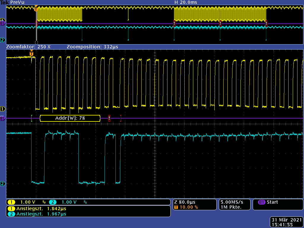
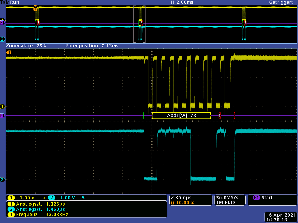
       - Addressing the 0x78 with ACK looks correct.
      - the data byte looks like 10101111
      - but from here on the USCI does inexplicable things. The SCL starts running, and running, and running; until the next frame starts. What happens there in the USCI?

    3. Setup as 2. same run, zoom area shifted for ~7ms to the next frame

      - The SCL has been running since the previous frame.
      - The first half of the address looks good.
      - From the fifth clock something goes wrong...
      - The last rising edge of SDA could be the attempt of a stop condition.
      - From here on the software stands at the dangerous while (UCB0CTL1 & UCTXSTP); loop (line 101). The frame 7ms later does not come any more.

    4. Setup: Master addresses the slave, but the slave does not respond / is not present. The MSP is exposed to a low EMC interference radiation.


      This looks fine.

    5. Setup same like 4. but the MSP is exposed to radiation that meets the requirement of the standard.


      - Things go wrong at the eighth clock.
      - The address given out by USCI is totally wrong. The first four bits of the address 0x78 are correct. After that there are wrong bits!
      - Also here the software stands at the dangerous while (UCB0CTL1 & UCTXSTP); loop (line 101). The frame 7ms later does not come any more.

    Once again, yes we annoy the MSP with radiation. But for the misbehavior of the USCI, which can be seen in the oscilloscope recordings, there is neither an explanation nor an indication for work arrounds.

    So we need help urgently! Please forward this support request to the 2nd level support in Freising.

    Thanks you.

    Best regards,

    Peter

  • Hi Peter,

    Let us communicate via email to help you solve the problem quickly.

    Thanks!

    Best Regards

    Johnson

**Attention** This is a public forum