This thread has been locked.

If you have a related question, please click the "Ask a related question" button in the top right corner. The newly created question will be automatically linked to this question.

SD16 VCC Measurement Errors

Other Parts Discussed in Thread: MSP430F2013, MSP430FE4272

Hey everyone,

I have been playing around with the SD16 again and am having some trouble measuring VCC correct using the internal resistor divider on A5. My MCLK is 16MHz. My code is as follows:


SD16CTL = SD16REFON + SD16SSEL_1 + SD16XDIV_2; // Internal Reference, SMCLK, /16

SD16INCTL0 = chan; // Fourth sample (implied), read 'chan'
SD16CCTL0 = SD16IE + SD16SNGL; // Enable interrupt, enable single mode
SD16CCTL0 |= SD16SC; // Start SD16 conversion


I am also using the I2C but this should not effect the measured value at all. I am constantly measuring about 0xB8C0 (~47300). Doing the math...

(0xB8C0-0x8000)*V_ref/(2^16)-V_ref/2) * 11.

This gives me a result of about 2.9V. I tested the V_ref (which is actually at 1.07V, but taking that into account makes my answer even less correct). My actual VCC measured by my Flukes is 3.38V. I have tried this on 4 separate MSP430F2013 chips.

I am out of ideas for what could be causing this. Does anyone have any ideas or has anyone had this problem before?

I am desperate for help!


Thanks in advance.

NJC

  • NJC said:
    (0xB8C0-0x8000)*V_ref/(2^16)-V_ref/2) * 11.

    Where did you get this formula? I didnt find it in the users guide (besides the fact that there's a bracket missing).


  • Ah! Thanks for catching that, it was a stupid mistake. That was not the equation I am actually using, but a combination of two mathematically equivilent equations that come from my interpretation of the datasheet.

    [ (0xB8C0-0x8000) * V_ref / (2^16) ] * 11

  • Well, okay.  After re-reading the users guide about the reference, the formula is seems to be okay. It' sjust that on my look at the SD16 description, I didn't see any formula.

    However, which channel are you reading? Should be 5 (0x05). If you're reading channel 6, the result falls in the range you'd expect there for room temperature.

    Also, did you apply the 100nF capacitor to VREF pin? If not, it might be that the reference breaks down or overshoots during conversion. Your Multimeter will only show an average value, but the momentary values the SD16 sees during conversion may be totally different.

    Keep in mind that the SD16 does not only use the reference for comparing the signal (delta stage), it actually adds the reference to a comparison buffer (sigma stage), so an unstable (unbuffered) reference can cause any effect, not just a linear raise of the result.

  • Jens-Michael,

    Thank you for the response! I can't believe I didn't just use my scope instead of my multimeter. I set the VREF to drive the external pin again and used my scope to capture the signal. WOW! I had no idea it was so "noisy". The signal looks like an RC circuit charging and discharging at a rate of about 4.8MHz with an upper peak voltage of 1.6V and a lower peak voltage at about .68V. On average this is about 1.2V.

    So, I was using the correct channel internally (A5), and after adding the capacitor to the VREF pin (which I didn't think would matter if I was only using the voltage internally), the scope shows a very clean 1.2V signal.

    Sadly, I am still measuring about the same value (about 0xB8A0) giving me a supply voltage of about 2.9V.

    My only guess is that the supply voltage is not as well regulated as it should be and whenever I do a conversion the voltage dips down due to the increase in current draw from the SD16. The 3.4V is coming from the LaunchPad, so I guess I should try a better regulated source.

    Any other suggestions?

  • Well, you can check VCC with your scope as well :)

    VCC, especially if not properly decoupled, is subject to heavey load changes. Some people who want high-quality conversion results, deactivate the CPU during the conversion (well, that works better for the AD1x converters and if not continuously sampling.).

    In case of the LaunchPad, I guess that both, the target as well as the programming MSP are powered by the same VCC.

    On some of the bigger MSPs, there is a separate AVcc/AVdd input whcih can be easily decoupled by a series resistor (few Ohms) and a capacitor. And can be separately routed to the supply, so ripple on VCC does nto affect the conversion result - unless you're sampling VCC itself (which you do).

  • Wow, I've been scouring the forum to find a solution to an SD16 conversion instability problem all afternoon, and I just came across this post.  I had two voltage dividers set up to give me a reference voltage and a sample voltage based on the MSP430FE4272 reference voltage, and the SD16 was giving me outputs that varied by around 2-4000/64000!

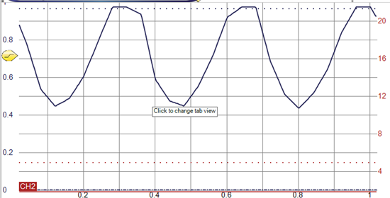
    After reading this I hooked up the scope to look at the reference voltage.  Here it is:

    That's right!  .4 V swing p-p on a .8 V signal.  It has a 339 ns period, meaning 3 MHz. I'm not sure where this is coming from, MCLK maybe?  I'm using the default clock settings, so it appears that it is running from DCO, whose default range is .65-6.1 MHz, and I guess that it is in the middle of that range.  

    Anyways, after adding liberal .1 uF electrolytic caps to my voltage dividers my variation is down to around 20-40/64000, which is within the range of the datasheet and totally livable.  

    So, to the next person that is getting rapid variations in ADC readings: try liberal use of coupling caps.  Now I understand why the old timers are so obsessed with them.


    Now can someone tell me a more efficient way to choose capacitors for my circuit board, or should I just throw a bit cap at every signal and power port?


  • Doug Jorgesen said:
    can someone tell me a more efficient way to choose capacitors for my circuit board, or should I just throw a bit cap at every signal and power port?

    Not every signal :)

    VCC itself should have a larger capacitor already (as requirement of the regulator). Some µF more won't hurt. A 100nF directly between (D)VCC and (D)VSS is always a good thing. Some MSPs ahve more than one DVCC, there every pin should have at least a 100nF, and a larger capacitance should be distributed mode or less evenly too (see the datasheet for minimum cap on DVCC). Some even have a VCore output which requires a capacitor (again, see datasheet)
    If the MSP has a separate AVCC input, then a series resistor of 10 or 22Ohm to VCC, followed by a 100nF ceramic/10µF Tantalum combo ensures a supply to the analog crcuitry that is mostly free from current ripple caused by the digital part.
    If you have the reference output enables, a 100nF ceramic/10µF Tantalum combo is recommended. On 1x series, this was mandatory. The 5x series can go without if the conversion clock is not too high and the reference is not output to a pin.
    And the RST pin should have a 10k pullup and a 10nF to VSS.

    For the rest, well, it's a good idea to have one 100nF on every supply of every chip that is clocked or has a clock. TTL/CMOS circuitry, whatever. The MSP itself should be content with the ones mentioned above.

  • Hi

    I am facing a similar situation. I am running the ADC of MSP430F2013 as SD16, there is an error on the measurements. I am measuring a voltage of a battery which with Fluke multimeter it shows 7.5V but when I run the ADC it show counts related to 7.35V. I am using the formula  Voltage = (Counts / 65536)*0.6 . I try everything you said in this forum including adding the caps an nothing has changed. Does anybody know if there is anything wrong with the formula or something else ?

    Thanks

  • The error is ~2%. This is well in the range of the reference tolerance. The reference is in the range of 1.14 to 1.26V, which gives a result range from 7.125V to 7.875V for a 7.5V input.

    On the 2013, INFOA segment contains calibration data, btu I'm not sure whether this includes calibration iformation for the reference too. (on 5x family devices, the TLV structure contains correction factors and offset infor for the ADCs)

    Alternatively, you may calibrate it yourself by applying a precision voltage and calculate the calibration value/correction factor yourself. 0.6 is just the starting point.

    One more thing: the correct formula is

    (counts/65535)*(Vref/2)
    Since 0 is 0, there are only 65535 steps to Vref

  • Hi Jens

    Thanks for your help !

    I don't have a way to use external reference voltage because all I/O are being used . Are you recommending that I should find exactly what the internal reference voltage value is based on the right voltage applied and then figure determine the right ADC counts ? Because if this is your recomendation I will have an issue since I will me doing multiple boards which it could be a different variation from one the another. 

  • marcelo deoliveira said:
    Are you recommending that I should find exactly what the internal reference voltage value is based on the right voltage applied and then figure determine the right ADC counts ? Because if this is your recomendation I will have an issue since I will me doing multiple boards which it could be a different variation from one the another. 


    Yes, that's why it is called 'calibration' and not 'using a universal constant'.
    On several MSPs, this is done at factory, even for two different temperatures (to allow temperature compensation).

    We use our own approach: on Startup, if there is no calibraiton value stored in info memory, our metering devices enter calibration mode. Now they expect an input voltage of 1V (+-10%). The device does converison after conversion until the result is in range for a certain time and stable. Then it switches to next calibraiton point, 2V input voltage (again +-10%).
    After the two voltages have been received, offset and gain are calculated and stored. This repeats for all six inputs.
    On next start, the device works with these values.
    Externally, we only apply 1.0 and 2.0V (precision voltage source) with a switch to the MSP voltage input pin. If you have a jumper on the board that allows breaking the connection to your signal source and the MSP, so you can pull it and connect the constant voltage instead, then it is a snap.
    This method is used on our metering devices that take 0-10V input voltage (with resistor divider) or 4-20mA (here we inject a constant current, based on an OpAmp and shunt resistor as regulator).
    On a different project with precision components (and more PCB space), we use a shunt regulator as precision voltage source and do not do any calibration. But there we don't have voltage dividers on the inputs and we require the reference voltage anyway for the OpAmps.

**Attention** This is a public forum