This thread has been locked.

If you have a related question, please click the "Ask a related question" button in the top right corner. The newly created question will be automatically linked to this question.

MSP430 hardware design

Other Parts Discussed in Thread: MSP430F5506, CC1125

Hello!

I am currently working on a hardware design for an MSP430F5506. I however have never done a design for an MSP430 before and I am not really sure what pins I need and so on. Below is a schematic picture of the initial design I recently started:


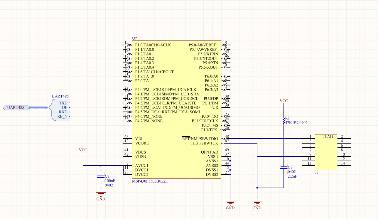
I have just connected a JTAG interface and imported the UART interface from my RS-485 transciever. I have no need for any USB connection as I will use the JTAG interface for programming and so on. I will also implement a SPI interface to a CC1125 transciever alongside the UART interface. I am wondering about such pins as Vcore? I am not sure if I need it or not? And the Vusb, V18, DP, DM, PUR and Vbus connections I can just leave unconnected then?

  • Hi Mikael,

    A few notes:

    You need to have VCC on your JTAG connector as well. You'll have to decide if you want to have the board be powered from the JTAG programmer, or externally, to determine whether you should connect JTAG pin 2 or pin 4 to Vcc. If you want to support both setups, you can put a jumper to allow you to switch between the two connections. (this is what we do on our target boards, if you see the schematics in the Hardware Tools User's Guide)

    The TI FET target boards are usually a good thing to look at if you want to have a starting point of the correct minimum connections. For the F5506 you can look at the MSP-TS430RGC64USB. While this is for a superset device with more pins than yours, it will give you an idea of what you ned to have on your board.

    Vcore is absolutely necessary - you need to put a 470nF cap to ground on this pin (this is listed in the datasheet under recommended operating conditions).

    For the USB pins that you listed, you can find the correct connections for them when you are not using the USB module by seeing the 5xx User's Guide section 1.6 "Connection of Unused Pins". Looking here you'll see that V18, VUSB, and DP/DM should be left open, but PUR and VBUS should be tied to GND (also see footnote 3 on that table, which says that a 1M resistor to GND is recommended on PUR).

    Hope this helps get you started!

    Regards,

    Katie

  • Mikael Hygren said:
    I am wondering about such pins as Vcore? I am not sure if I need it or not?

    VCore is the regulator output for the CPu core voltage. It needs 470nF attached and nothing else. Without the 470nF, the CPU won't operate stable, if at all.

**Attention** This is a public forum