


Hello,
I’m using the msp430f5438A, with CCs 5.3.
And I want to use with the I2C module ( my first time) in order to read data from I2c simulator (AARDVARK I2c simulator)
I get the following wave diagram:
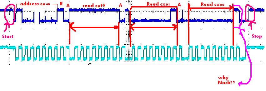 the Nack is Unexplained .
i use the following code:
****************************************
int main(void)
{
Uint16 rslt = 0;
	Uint16 tmpDelay = 10;// init value.
	 __bic_SR_register(GIE); // disable interrupt.
	PortCnfg();
	ClockCnfg();// 16mhz
	TimerA1Cnfg();//timer interrupt of 10Hz.and blink the led
	I2cCnfg ();
	__bis_SR_register(GIE);      // enable interrupts

	 while (1)
	 {
	   rslt = I2cRd  ( 3);// read 3 data
	   while ( tmpDelay--)// delay between conversion.
	   {
		__delay_cycles(30000);
	   }
	   tmpDelay = 1;
	 }
}


void I2cCnfg (void)
{
	 UCB1CTL1 |= UCSWRST;                      // Enable SW reset

	 //The USCI module is configured as an I2C slave by selecting
	 //the I2C mode with UCMODEx = 11 and
	 //UCSYNC = 1 and clearing the UCMST bit
	 // also, UCSSELx bits is Modify only when UCSWRST
	 UCB1CTL0 = UCMST + UCMODE_3 + UCSYNC;     // I2C, Master, synchronous mode

	 UCB1CTL1 = UCSSEL__SMCLK + UCSWRST;// Use SMCLK, keep SW reset
	 UCB1CTL1 &= UCTR;// config as read (DEFAULT).
	 UCB1BR0 = 160;            // fSCL = SMCLK/160 = ~100kHz
	 UCB1BR1 = 0;
	 UCB1I2CSA = 0x48;         // Slave Address is( 16 bits) 048h
	 UCB1CTL1 &= ~UCSWRST;                     // Clear SW reset, resume operation
}

Uint16 I2cRd  ( Uint16 numRd)
{
	Uint16 NumOfRd = numRd;
	UCB1CTL1 &= ~UCTR;// config as read.
	 // this section is for reading.
	   while (UCB1CTL1 & UCTXSTP); // Ensure stop condition got sent
	   	   	   	   	   	   	// ensure to close any open transaction
	   	   	   	   	   	   // before you start new one
	   UCB1CTL1 |= UCTXSTT;  // I2C start condition/transaction.
//	   __no_operation();
	   while(UCB1CTL1 & UCTXSTT); // Start condition sent?
	   __no_operation();                       // For debugger
	   while (NumOfRd--){// number of reading, without repeated start
		   while (!(UCB1IFG & UCRXIFG));//UCRXIFG is automatically reset when UCxRXBUF is read
		   I2cRdData [I2cRdIndx] = UCB1RXBUF;
		   I2cRdData [I2cRdIndx] |= ((UCB1IFG & UCNACKIFG) == 0)? 0: 0xF000;// recording  nack/ack.
		   	//UCNACKIFG is automatically cleared when a START condition is received.
		   	UCB1IFG &=~ UCNACKIFG;// clear manually.
		   	I2cRdIndx++;
		   	I2cRdIndx%=I2C_RX_BUF_SIZE;
	   }
	   UCB1CTL1 |= UCTXSTP;// I2C stop transction
	   return TEST_OK;
}
***************************************
I want to emphasize:
1. all the data read correctly from the simulator ( 0xFF 0x01 0x00)
2. in the above code , i record the data and the accompanying nack/ack . no nack is record. the nack recognize
only by scope. without observing the data by the scope i wouldn't recognize the problem.
is anyone can explain the Nack appearance ?
thanks.

