This thread has been locked.

If you have a related question, please click the "Ask a related question" button in the top right corner. The newly created question will be automatically linked to this question.

Interfacing MODBUS RTU HMI with MSP432 Launchpad

Other Parts Discussed in Thread: MAX232, ENERGIA

Hi Everyone,

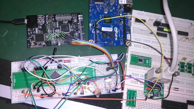
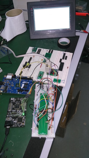
I'm currently working with a MSP432 launchpad driving a HMI display using modbus RTU protocol via RS232.
The problem I encountered the past few days:

  • the built in DC to DC converter of the XDS110 gets burning hot from time that it is powered on.
  • Unusual hangups also encountered.
    hmi
    rs232

  • I used a MAX232 on P3.2 and P3.3 on these pins to convert the UART to RS232 level. The problem is I'm not getting the same echoed message expected. But the amazing thing, I have (2) subroutine that consist of reading the bit switch on the HMI panel and one is displaying the floating point number. If I use only one of them, things works fine but if im going to read the switch status and display a floating point number. both will not work.

  • The same code I used to Intel Galileo and it works fine even if the (2) subroutines are in place. That's why I am able to identify it is not with the coding. below is the copy of my tested code.
byte y = 0;
int val;
byte lowCRC; //Low byte of CRC
byte highCRC;
byte valH; //final CRC value
byte valL;

byte slaveID = 0x01;
byte Func_Code;
byte StartAddrH;
byte StartAddrL;
byte numofPointsH;
byte numofPointsL;
byte storage[13];
byte storage1[6];
byte numofBytes;
byte LowbyteH;
byte LowbyteL;
byte HighbyteH;
byte HighbyteL;
byte a;
byte b;
byte c;
byte d;
byte data;
byte ByteCount;
float z = random(65535.00);
int LED = 13;

int x;

int addr = 0x23;
byte HIGH_BYTE = 0;
byte LOW_BYTE = 0;
void setup()
{
pinMode(LED,OUTPUT);
Serial.begin(9600);
Serial1.begin(9600); //port used to MAX232, P3.2 and P3.3

}

void loop(){
ModRTU_switch(); //function to read the bit switch
y = storage1[3]; //status of the bit switch
Serial.println(z,3); //value of the float
SerialPrintFloatIeee754(z); //get the binary representation of float
delay(500);

switch(y){

      case 0x01:                               //if bit switch is ON, send random floating number on the numerical input display
            z = random(0.000,65535.000);

            ModRTU_Read_PWM();                 //subroutine for writing to the numerical input display
            digitalWrite(LED,HIGH);            //turn on LED
            delay(500);
            break;


      default:                                //if bit switch is zero, turn off LED
          // z = 0.000;
        //   ModRTU_Read_PWM(); 
           digitalWrite(LED,LOW);              
           delay(500);
           break;
}
  Serial1.flush();
}

void ModRTU_switch(){

slaveID = 0x01;
Func_Code = 0x01;
StartAddrH = 0x00;
StartAddrL = 0x00;
numofPointsH = 0x00;
numofPointsL = 0x01;

byte buffer[] = { slaveID, Func_Code, StartAddrH, StartAddrL, numofPointsH, numofPointsL};
int size = sizeof(buffer);
ModRTU_CRC(buffer, size);
byte buffer_w_checksum[] = { slaveID, Func_Code, StartAddrH, StartAddrL, numofPointsH, numofPointsL, lowCRC, highCRC};

Serial1.write(buffer_w_checksum,8);
if(Serial1.available() > 0){
while(Serial1.available()){
for(int i = 0; i < 6; i++){
storage1[i] = Serial1.read();
}
}
}

Serial.print("Slave ID is "); //print out of the echoed data from Modbus HMI master
Serial.println(storage1[0],HEX); //
Serial.print("Function Code is "); //
Serial.println(storage1[1],HEX); //
Serial.print("No. of points is "); //
Serial.println(storage1[2],HEX); //
Serial.print("Data is "); //
Serial.println(storage1[3],HEX); // status of the bit switch
Serial.print("Low CRC is "); //
Serial.println(storage1[4],HEX); //
Serial.print("High CRC is "); //
Serial.println(storage1[5],HEX); //

}

void ModRTU_Read_PWM(){

slaveID = 0x01;
Func_Code = 0x10;
StartAddrH = 0x00;
StartAddrL = 0x00;
numofPointsH = 0x00;
numofPointsL = 0x02;
numofBytes = 0x04;
LowbyteH = b;
LowbyteL = a;
HighbyteH = d;
HighbyteL = c;

byte buffer[] = { slaveID, Func_Code, StartAddrH, StartAddrL, numofPointsH, numofPointsL, numofBytes, LowbyteH, LowbyteL, HighbyteH, HighbyteL /*, highCRC, lowCRC*/};
int size = sizeof(buffer);
ModRTU_CRC(buffer, size);
byte buffer_w_checksum[] = { slaveID, Func_Code, StartAddrH, StartAddrL, numofPointsH, numofPointsL, numofBytes, LowbyteH, LowbyteL, HighbyteH, HighbyteL, lowCRC, highCRC};
Serial1.write(buffer_w_checksum,13);
if(Serial1.available() > 0){
while(Serial1.available()){
for(int i = 0; i < 13; i++){
storage[i] = Serial1.read();
}
}
}

Serial.print(storage[0]); //printout of the echoed data from modbus HMI master
Serial.print(storage[1]);
Serial.print(storage[2]);
Serial.print(storage[3]);
Serial.print(storage[4]);
Serial.print(storage[5]);
Serial.print(storage[6]);
Serial.print(storage[7]);
Serial.print(storage[8]);
Serial.print(storage[9]);
Serial.print(storage[10]);
Serial.print(storage[11]);
Serial.println(storage[12]);

Serial1.flush();
}

void ModRTU_CRC(byte buf[], int len)
{

uint16_t crc = 0xFFFF;
for (int pos = 0; pos < len; pos++) {
crc ^= (uint16_t)buf[pos]; // XOR byte into least sig. byte of crc
for (int i = 8; i != 0; i--) { // Loop over each bit
if ((crc & 0x0001) != 0) { // If the LSB is set
crc >>= 1; // Shift right and XOR 0xA001
crc ^= 0xA001;
}
else // Else LSB is not set
crc >>= 1; // Just shift right
}
}
valH = crc >> 8;
valL = crc & 0x00FF;
highCRC = valH;
lowCRC = valL;
val = crc;
// Note, this number has low and high bytes swapped, so use it accordingly (or swap bytes)

}

void SerialPrintFloatIeee754(float RealNumber)
{
byte* ArrayOfFourBytes;
ArrayOfFourBytes = (byte*) &RealNumber;

if (ArrayOfFourBytes[3]>=128){
Serial.print("1");
}
else{
Serial.print("0");
}

Serial.print((ArrayOfFourBytes[3]/64)%2, BIN);
Serial.print((ArrayOfFourBytes[3]/32)%2, BIN);
Serial.print((ArrayOfFourBytes[3]/16)%2, BIN);
Serial.print((ArrayOfFourBytes[3]/8)%2, BIN);
Serial.print((ArrayOfFourBytes[3]/4)%2, BIN);
Serial.print((ArrayOfFourBytes[3]/2)%2, BIN);
Serial.print( ArrayOfFourBytes[3]%2, BIN);
Serial.print((ArrayOfFourBytes[2]/128)%2, BIN);
////Serial.print(" ");
Serial.print((ArrayOfFourBytes[2]/64)%2, BIN);
Serial.print((ArrayOfFourBytes[2]/32)%2, BIN);
Serial.print((ArrayOfFourBytes[2]/16)%2, BIN);
Serial.print((ArrayOfFourBytes[2]/8)%2, BIN);
Serial.print((ArrayOfFourBytes[2]/4)%2, BIN);
Serial.print((ArrayOfFourBytes[2]/2)%2, BIN);
Serial.print( ArrayOfFourBytes[2]%2, BIN);
Serial.print((ArrayOfFourBytes[1]/128)%2, BIN);
Serial.print((ArrayOfFourBytes[1]/64)%2, BIN);
Serial.print((ArrayOfFourBytes[1]/32)%2, BIN);
Serial.print((ArrayOfFourBytes[1]/16)%2, BIN);
Serial.print((ArrayOfFourBytes[1]/8)%2, BIN);
Serial.print((ArrayOfFourBytes[1]/4)%2, BIN);
Serial.print((ArrayOfFourBytes[1]/2)%2, BIN);
Serial.print( ArrayOfFourBytes[1]%2, BIN);
Serial.print((ArrayOfFourBytes[0]/128)%2, BIN);
Serial.print((ArrayOfFourBytes[0]/64)%2, BIN);
Serial.print((ArrayOfFourBytes[0]/32)%2, BIN);
Serial.print((ArrayOfFourBytes[0]/16)%2, BIN);
Serial.print((ArrayOfFourBytes[0]/8)%2, BIN);
Serial.print((ArrayOfFourBytes[0]/4)%2, BIN);
Serial.print((ArrayOfFourBytes[0]/2)%2, BIN);
Serial.println( ArrayOfFourBytes[0]%2, BIN);

Serial.flush();

d = ArrayOfFourBytes[3];
c = ArrayOfFourBytes[2];
b = ArrayOfFourBytes[1];
a = ArrayOfFourBytes[0];

return;
}

Thanks,
Leo

  • Leo,
    It looks like your MSP432 is overheating. This is a known flaw that happens when touching the capacitors near the USB port. It is permanent and effects the performance of the MSP. Can you send me your address for a replacement?

    Best regards,
    Cameron
  • Hi Cameron,

    This is exactly the one I'm encountering about that capacitor.
    Just want to ask if there is a known issue on it's Serial Ports performance due to its IC Manufacturing Process or is this only affected by XDS110 DC to DC converter why it is overheating? The MSP432 doesn't get hot itself. I am powering the HMI with External +24 Volts and the MAX232 with a separate +5 Volts and isolated the MSP432 Launchpad alone and it is continuously overheating.

    I am about to submit my design and short of time because I spent a lot of time debugging the code for some anomalies until I tried this with Intel Galileo and ATmega2560 and my code worked fine. I need a High pin count MCU preferably an ARM and I see this for my benchmarking. What causes this and a solution for me to save time redrawing the whole schematic and evaluating the firmware again? I appreciate if the replacement can reach my place within this week or next week. My address is below. Thanks for the honest answer..

    Leo Pestañas
    Senior Application Engineer
    BPE Synergy Engineering Services SDN. BHD.
    4-1 & 4-2 Jalan TBC 9 Taman Bukit Cheng Melaka Malacca Malaysia 75250
    Office No.: +606-312-2724
    Fax No.: +606-312-3428
    Email: eng3@bpese.com
  • Leo,
    I have a request in to have a new LaunchPad shipped out to you. I'll keep you filled in as I learn the timing details.

    A common "patch" for this problem, is to put electrical tape around the portion of the board near the USB port, as it is very easy to touch the capacitor in question when connecting or disconnecting the USB.

    I don't have a lot of information as to why this happens (I've looped in those who do), but when I've ecperienced this before I would lose UART connection with my PC among other things. I am to understand that this is a PCB flaw, not an IC flaw.

    I'm doing everything I can to help you out, I'll keep you posted. :-)
  • Leo,
    This post explains the failure in detail.

    e2e.ti.com/.../490273
  • Hi Mr. Cameron,

    I will do your advice once I receive the new MSP432 Launchpad.
    We are about to find out this coming week upon it's arrival to our office.
    Last Friday, I did power up the IC alone by removing all jumper blocks and not deriving power from the USB at all.
    I used the +3.3V of Intel Galileo to Power up the MSP432 IC, seperate 24VDC power supply for HMI and the +5V of Intel Galileo to the MAX232.
    All GND's tied up nicely. But no luck, still the unusual hangup is there. Do you think it still because of PCB flaw?
    I still have (5)MSP432 IC and I can change to my existing launchpad if ever.

    Leo Pestañas
    Senior Application Engineer
    BPE Synergy Engineering Services SDN. BHD.
    4-1 & 4-2 Jalan TBC 9 Taman Bukit Cheng Melaka Malacca Malaysia 75250
    Office No.: +606-312-2724
    Fax No.: +606-312-3428
    Email: eng3@bpese.com
  • Leo,
    My understanding is that something is damaged on the XDS110 side of the board, and that applying power to the MCU will back feed that component and the problem will persist. Unfortunately, you may have to weight for the new Launchpad.
  • Hi Mr. Cameron,

    So, even if I remove all the jumpers on the jumper blocks will not isolate the XDS110 from the MSP432.
    I saw on the schematic that the JTAG will still remain connected via IC111 and S101.
    I'll just wait for the new unit then and try the suggested solution. Thanks for the usual support.

    Leo Pestañas
    Senior Application Engineer
    BPE Synergy Engineering Services SDN. BHD.
    4-1 & 4-2 Jalan TBC 9 Taman Bukit Cheng Melaka Malacca Malaysia 75250
    Office No.: +606-312-2724
    Fax No.: +606-312-3428
    Email: eng3@bpese.com
  • Leo,
    My apologies, I didn't realize you were using an external debugger, yes, removing the jumpers should work. I'm told you will still need to plug in the USB on the XDS110 in order to power a switch or a mux for the external JTAG to work. It may be the case that you do not need to replace the MCU, you could try both ways. I'm not sure if the MCU is destroyed when this bug arises.
  • Hi Mr. Cameron,

    Yes, I don't want the XDS110 to connect to the target MCU onboard. I just want to test if isolating the debugger will make the MCU work normal by providing power separately and removing the jumpers.

    I will try to wire my sample IC on breadboard and test this. Will post the result soon it is done. Thanks.

    Leo

  • Looking forward to hearing what you find, Leo!
  • Hi Mr. Cameron,

    I received the MSP432 just today when I returned just now in the office.

    After trying several times with the new board and wiring an external MSP432, still no luck of making it work.

    I want to know how can I use the other channels of UART? like the UART1 and UART3?

    "Serial" is the "BCL_UART"(UART0) and "Serial1" is UART2 in the schematic.

    What I plan now is to receive the echo on the other RX of UART Channels.

    I tried the writing on "Serial1" and changing the receive part of code into "Serial.read" and no hangup was observed.

    I also tried coding the UART.h instructions but still hangs on receive part using the same channel of UART.

    If I remove the receive part of the code, everything will turn fine.

    I also noticed that the contents of the array are shifting locations after transmitting the (2)random numbers and checking the switch status, that's why the HMI rejects the incoming instruction.

    The number will display random floating point numbers and the other will give the correct message echo to read the switch status works fine if they are not executed in sequence in the program(one must remain to work fine).

    If the switch status is checked and display a random number, everything will still hang after (2)random numbers displayed.

    The Intel Galileo is just to put power on MAX232. I hope this issue can be resolved soon.

    One project, I reverted back already to Atmega2560 due to urgency.

    Thanks,

    Leo

  • Leo,

    In the future, please format your code using the code format button. I've already edited your first post to do this. Now we can use line numbers to reference the code and it is more readable.

    It sounds like msp is waiting for a vairable to be transmitted, so it may be a timing issue or setup issue.

    Can you try doing your communication via the USB on the launchpad with a terminal on the PC, and faking the HMI? This will eliminate the code portion or the hardware portion. It may be that the code is set up correctly for the Intel chip but not the MSP432.

    I'm having a hard time following where the code is hanging, can you give me the line numbers? Can you give me logic analyzer captures of what the communications look like when the code hangs?

    Which array are you referring to when you say you are seeing it's contents shifting?

    How do you have your UART set up?

    UART1 TX is pinned out to pin J4 34, and RX is pinned to the RGB LED Blue Jumper. You could remove this jumper and use it there.

    UART3 TX (9.7) and RX (9.6) is on the fan out at the bottom of the board.
  • Hi Mr. Cameron,

    Finally, I got it working with the same setup.

    Please see the code and see the line where it is particularly hanging.

    I commented it out along the code.

    At least, we can avoid that UART hangup in the future if we are going to use MODBUS.

    modbus_trial.zip(The code imported from Energia to CCS)

    #include "eusci.h"
    #include "uart.h"
    
    byte y = 0;
    int val;
    byte lowCRC;      //Low byte of CRC
    byte highCRC;
    byte valH;         //final CRC value
    byte valL;
    
    byte slaveID = 0x01;
    byte Func_Code;
    byte StartAddrH;
    byte StartAddrL;
    byte numofPointsH;
    byte numofPointsL;
    byte storage[13];
    byte storage1[6];
    byte numofBytes;
    byte LowbyteH;
    byte LowbyteL;
    byte HighbyteH;
    byte HighbyteL;
    byte a;
    byte b;
    byte c;
    byte d;
    byte data;
    byte ByteCount;
    float z;
    int LED = 13;
    
    
    int x;
    
        int addr = 0x23;
        byte HIGH_BYTE = 0;
        byte LOW_BYTE = 0;
     
    void setup()
    {
      pinMode(GREEN_LED,OUTPUT);
      Serial1.begin(9600);
    }
    
    void loop(){
        ModRTU_switch();              //function to read the bit switch
        y = storage1[3];              //status of the bit switch
          
        switch(y){
          
              default:                           //display "0.00" if switch on HMI is "OFF"
                   z = 0.000;
                   SerialPrintFloatIeee754(z);   //get the binary representation of float
                   ModRTU_Read_PWM(); 
                   digitalWrite(GREEN_LED,LOW);              
                   delay(1000);
                   
                   do{                                //loop forever if switch status is not "1"
                        ModRTU_switch();              //function to read the bit switch
                        y = storage1[3];              //status of the bit switch
                   }
                   while(storage1[3] != 1);
                   Serial1.flush();
                   break;
                 
              case 1:                               //if bit switch is ON, send random floating number on the numerical input display
                    z = random(65535.000);
                    SerialPrintFloatIeee754(z);   //get the binary representation of float
                    ModRTU_Read_PWM();                 //subroutine for writing to the numerical input display
                    digitalWrite(GREEN_LED,HIGH);            //turn on LED
                    delay(1000);
                    Serial1.flush();
                    break;        
        }
     
    }
    
    
    void ModRTU_switch(){
      
       slaveID = 0x01;
       Func_Code = 0x01;
       StartAddrH = 0x00;
       StartAddrL = 0x00;
       numofPointsH = 0x00;
       numofPointsL = 0x01;
       
       byte buffer0[6] = { slaveID, Func_Code, StartAddrH, StartAddrL, numofPointsH, numofPointsL};
       int size = sizeof(buffer0);
       ModRTU_CRC(buffer0, size);
       byte buffer_w_checksum0[8] =  { slaveID, Func_Code, StartAddrH, StartAddrL, numofPointsH, numofPointsL, lowCRC, highCRC}; 
       
      Serial1.write(buffer_w_checksum0,8);
      
      if(Serial1.available() > 0){
        while(Serial1.available() > 0){
          for(int i = 0; i < 6; i++){
            storage1[i] = Serial1.read();
          }
        }
      }
     
    }
    
    
    void ModRTU_Read_PWM(){
    
    slaveID = 0x01;
    Func_Code = 0x10;
    StartAddrH = 0x00;
    StartAddrL = 0x00;
    numofPointsH = 0x00;
    numofPointsL = 0x02;
    numofBytes = 0x04;
    LowbyteH =  b;
    LowbyteL =  a;
    HighbyteH = d;
    HighbyteL = c;
        
        byte buffer1[11] = { slaveID, Func_Code, StartAddrH, StartAddrL, numofPointsH, numofPointsL, numofBytes, LowbyteH, LowbyteL, HighbyteH, HighbyteL /*, highCRC, lowCRC*/};
        int size = sizeof(buffer1);
        ModRTU_CRC(buffer1, size);
        byte buffer_w_checksum1[13] = { slaveID, Func_Code, StartAddrH, StartAddrL, numofPointsH, numofPointsL, numofBytes, LowbyteH, LowbyteL, HighbyteH, HighbyteL, lowCRC, highCRC};
        Serial1.write(buffer_w_checksum1,13);
    
    //   if(Serial1.available() > 0){                  //  Guaranteed the system will hang if you uncomment this code
    //    while(Serial1.available() > 0){              //
    //      for(int i = 0; i < 13; i++){               //
    //        storage[i] = Serial1.read();             //
    //      }                                          //
    //     }                                           //
    //   }
    
    
    }
    
    void ModRTU_CRC(byte buf[], int len)
    {
      
      uint16_t crc = 0xFFFF;
      for (int pos = 0; pos < len; pos++) {
        crc ^= (uint16_t)buf[pos];          // XOR byte into least sig. byte of crc
        for (int i = 8; i != 0; i--) {    // Loop over each bit
          if ((crc & 0x0001) != 0) {      // If the LSB is set
            crc >>= 1;                    // Shift right and XOR 0xA001
            crc ^= 0xA001;
          }
          else                            // Else LSB is not set
            crc >>= 1;                    // Just shift right
        }
    }
      valH = crc >> 8;
      valL = crc & 0x00FF;
      highCRC = valH;
      lowCRC  = valL;
      val = crc;
      // Note, this number has low and high bytes swapped, so use it accordingly (or swap bytes)
        
    }


    Thanks for the help. I will still provide the waveforms and info that you need as requested.


    Best Regards,

    Leo Pestañas

    Senior Application Engineer

    BPE Synergy Engineering Services SDN. BHD.

    4-1 & 4-2 Jalan TBC 9 Taman Bukit Cheng Melaka Malacca Malaysia 75250

    Office No.: +606-312-2724

    Fax No.: +606-312-3428

    Email: eng3@bpese.com

  • Glad to hear its working! I am curious why that piece of code works earlier in, but not at the commented location.

    Do you need anything else from me regarding this issue?
  • Hi Mr. Cameron,

    As of now, it looks good except reading back the echo message of the floating point number immediately.
    This code both simulated and debugged using Energia and CCS compared
    with the results of the 1st code using Arduino and Intel Galileo which is unedited version of this new code.
    But reading and writing alone on the HMI register works fine but must be in slow timing iteration on the loop even if I increase the baud rate.
    I will try this code on other brand of HMI since this brand is going to be obsolete as per the supplier.
    I just need to make the existing project design working.
    Again, thanks for helping us for some hint on handling the MSP432.
    The 1st launchpad is confirmed damaged because it is still overheating and the new one is not.
    I consider this issue as of now closed as of this writing.

    Best Regards,
    Leo Pestañas
    Senior Application Engineer
    BPE Synergy Engineering Services SDN. BHD.
    4-1 & 4-2 Jalan TBC 9 Taman Bukit Cheng Melaka Malacca Malaysia 75250
    Office No.: +606-312-2724
    Fax No.: +606-312-3428
    Email: eng3@bpese.com

**Attention** This is a public forum