This thread has been locked.

If you have a related question, please click the "Ask a related question" button in the top right corner. The newly created question will be automatically linked to this question.

MSP430G2553: BSL synchronization failure

Part Number: MSP430G2553


I have a G2553 installed in a breadboard with a 47K pullup resistor on /RST, and I'm testing BSL with a USB-to_serial adapter that I know from other test works fine.  When I run BSLDEMO2, I appear to get all the right signals, but nothing is transmitted from the G2553, and I get the synchronization failed message.  I have things connected as follows:

Adapter..........G2553

GND...............GND (20)

3.3V................Vcc (1) w 10 ufd

DTR................/RST (16) with 47K pullup

RTS.................Test (17)

TXD.................P1.5 (7)

RXD.................P1.1 (3)

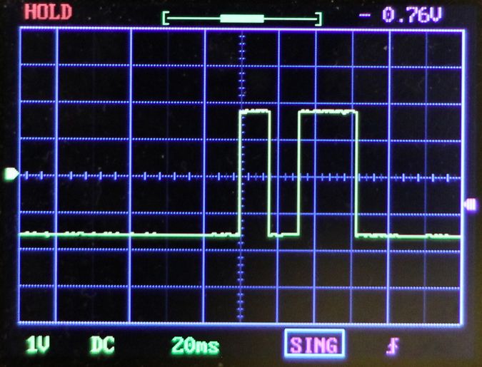
On my scope I see Test starts out low, then goes high for 10ms, back low for 10ms, high for 20ms, then back low.

/RST starts low, then goes high for 50ms, then back low.

I believe these are the patterns described in slau319 if I assume /RST goes back low because it doesn't receive an ack.

There is transmission of data on the adapter's TXD line, but nothing ever happens on P1.1.  It just stays a floating input when it should be output high.

So apparently everything is happening as it's supposed to, but the G2553 just never engages.  I've tried reversing RXD and TXD, with no success.

Any suggestions would be appreciated.

  • Hi George,
    Can you post scope captures with the two signals together? This would be the most helpful.

    Are you seeing the SYNC character (80h) being sent to the BSL? I'm not aware of an ACK sent before this.
  • At the moment I'm limited to a single working channel, but I'll see if I can rig something up to show both signals.

    But I'd like to put the triggering issue aside for the moment and address a more fundamental problem.  I set up code in the G2553 such that on boot it jumps to the cold start BSL vector, so the triggering on /RST and Test isn't needed.  Then I tried using bsldemo2 to just read a section of memory.  Here's the result:

    C:\TI>bsldemo2.exe -cCOM4 -pPW1.txt -r0xD000 0x0100 read.txt +u
    MSP430 Bootstrap Loader Communication Program (Version 2.01)
    Read memory to file: read.txt Start: 0xD000 Length 0x100
      Read memory Start: 0xD000 Length 240
    ERROR: Communication Error!

    The PC transmits a series of bytes, begining with what looks like an 0x80, over a period of 35 ms.  During that period, the 2553 responds with four bytes spaced fairly evenly. The first one looks a lot like a 0x90 in 8/E/1, and I'd guess the other three are too.

    The password file looks like this:

    @FFE0
    FF FF FF FF FF FF FF FF FF FF FF FF FF FF FF FF
    FF FF FF FF FF FF FF FF FF FF FF FF FF FF C0 10
    q

    The driver for my adapter is set for 9600 baud, 8/E/1, which is what slau319 says is used.

    So actually, everything seems to be working.  But something is obviously wrong.  There's no question I have the right pins, and the port settings seem right.  But bsldemo2 thinks something is wrong.

    I should say that I have used this adapter to flash software to a G2231 using the very simple custom protocol provided by TI, and it all works fine.

    So I'm puzzled why it doesn't work.  I'm also curious where the "length 240" comes from, unless that's the first of two packets.  The 2553 never does start sending the read data, so it appears to be a baud rate mismatch or something like that.

    I hope you can indentify what I'm doing wrong.  I'm assuming that bsldemo2 has actually worked with a G2553 for someone at some point in the past.

  • Hi George,

    did you check if the code you initially programmed does not disable the BSL as described in slau319

    Best regards,
    Dietmar

  • Yes, I have 0000 at that location. But FFFF doesn't work either, so that's not the problem.
  • Ok I've figured out the problem with the /Reset Test BSL initiation sequence.  Both DTR and RTS do exactly what they are supposed to do (per slau319), except that DTR is inverted.  So as it is, it does the opposite of the required pattern, and goes back into reset at the end.  So it's no wonder it doesn't work.  RTS is fine though.  I'm not sure why only one would be backwards, but I guess all of this originates back when computers had real serial ports, so who knows what was assumed about polarity.  But you know, we've had these USB-to-serial adapters for a while now, and I would have hoped TI would have made a version of BSLDEMO that worked with them straight through, without the need for an inverter.  If there is such a version, someone please give me a link.

    Of greater concern though is the communications errors I get when I bypass the special boot sequence and jump straight into the BSL cold start.  Bytes are being transmitted in both directions, so unless I've given an illegal instruction, it pretty much has to be either a baud rate mismatch or a parity mismatch.  I can see the BSL sending at 8/E/1 because I can see the zero parity bit when 0x90 is transmitted.  But I can't be sure about BSLDEMO2 because 0x80 has a one partiy bit, which is the same as the stop bit.  Is it also using even parity?

    I know this is in the deprecated folder, but the chip is still being sold, and it still has BSL in ROM, so there ought to be software that works.

  • Here are three additional runs.  The first one is significant in that it appears to have finished, and it says it is sending the password, while the last two don't mention that.  If the password isn't being sent, that could explain why there's a failure.  In fact, the error is the same if I don't include the password file at all.  And yes, I'm positive the password is correct.

    C:\TI>BSLDEMO2.EXE -cCOM4 -pPW.TXT -m2 +u
    MSP430 Bootstrap Loader Communication Program (Version 2.01)
    Number of mass erase cycles set to 2.
    No Device reset - BSL called from user program ---------------------
    Transmit PSW file "PW.TXT"...
    BSL version: 2.03 - Family member: 2553 - Process: 0060
    Prog/Verify: 0.0 sec - Over all: 50457.4 sec

    C:\TI>BSLDEMO2.EXE -cCOM4 -pPW.TXT -m2 -rD000 40 saveit.txt +u
    MSP430 Bootstrap Loader Communication Program (Version 2.01)
    Number of mass erase cycles set to 2.
    Read memory to file: saveit.txt Start: 0xD000 Length 0x40
      Read memory Start: 0xD000 Length 64
    ERROR: Communication Error!

    C:\TI>BSLDEMO2.EXE -cCOM4 -pPW.TXT -m2 +uv PW.TXT
    MSP430 Bootstrap Loader Communication Program (Version 2.01)
    Number of mass erase cycles set to 2.
    Verify"PW.TXT"...
    Check starting at ffe0, 32 bytes... Error: 7
    ERROR: Communication Error!

    I don't understand what's happening.  Can someone please tell me what I'm doing wrong?

    Edit:

    Here's another successful run, this time involving a segment erase, and again explicitly stating it sent the password.  So apparently it isn't sending the password for all password-protected commands.  Why would that be?  How can I make it do that?

    C:\TI>BSLDEMO2.EXE -cCOM4 -pPW.TXT -eE000 +u
    MSP430 Bootstrap Loader Communication Program (Version 2.01)
    Transmit PSW file "PW.TXT"...
    BSL version: 2.03 - Family member: 2553 - Process: 0060
    Erase Segment: 0xE000
    Prog/Verify: 0.0 sec - Over all: 0.1 sec

    And this one completed too, but completely ignored the read command even though the password was sent.

    C:\TI>BSLDEMO2.EXE -cCOM4 -rD000 40 saveit.txt -1 -pPW.TXT -eE000 +u
    MSP430 Bootstrap Loader Communication Program (Version 2.01)
    Transmit PSW file "PW.TXT"...
    BSL version: 2.03 - Family member: 2553 - Process: 0060
    Erase Segment: 0xE000
    Prog/Verify: 0.0 sec - Over all: 0.1 sec

    I still don't understand what's going on.  But at least I think the "communication errors" aren't really that.

  • I think I finally figured it out.  Since I wasn't using the DTR and RTS signalling pattern, I used the +u parameter in the BSLDEMO2 command line, which says to skip sending that pattern.  But looking at the source code for the program, for some reason it skips sending the password  on several commands if +u is used.  And that means those commands will fail on the G2553 because it is expecting the password.

    So I went back and tried it again without the +u, just letting it do the DTR/RTS signalling even though nothing is connected to those lines, and both the read and verify commands worked fine.  So I think that's the answer.

    That leaves the issue of the inverted DTR line.  Can anything be done about that in software?  It seems a shame to add parts for an inverter when it could be fixed in software.  Does TI offer a version without that inversion?

  • Hi Geroge,

    good to hear that your resolved but the item with the inverted DATA TRANSMIT line is not really clear to me. Normally it works fine if you use e.g. a BSL rocket interface.

    So what kind of HW do you use as an interface between serial port of the PC and your target device. Maybe you can post a picture to get a better understanding. Also a scope shot of the signals would be nice then I can discuss this with BSL stakeholder in our team.

    Thanks,
    Dietmar

  • The first picture shows the RTS-Test line during the initial sequence.  As you can see, it's the same as the drawing in slau319 for parts like the G2553 with shared JTAG pins.  The second picture is the DTR-Reset line, and as you can see, it is inverted from the desired pattern.  It should be normally high, then go low to begin the pattern, then go back high at the right time, and stay there.  I apologize for not having a working 2-channel scope, but I believe these pictures show what's happening on each line, although not the relative timing between the two.  But it's obvious that DTR-Reset is inverted because it stays low after the sequence, which would keep the chip in permanent reset.  Of course it should stay high.

    Instead of using an external device like the Rocket, I want to embed a USB-to-serial chip in the project design so that flashing can be done with only a USB cable.  For that purpose I would use a CP2102.  For breadboarding purposes, I'm using a module containing a CP2102, its capacitors, a USB connector, and some indicator LEDs, but functionally it's just a CP2102.  This part is similar to other such USB bridge chips like the FT232 and CH340, and I believe TI also has one that's used in the Launchpad-G2.  These chips operate in a different environment than the one in which BSLDEMO was written, where computers actually had serial ports.  There are no inversions, or double-inversions, as described in the hardware section of slau319, and no need for DTR and RTS to provide power.  It would be nice if BSLDEMO worked directly with the USB bridge chips without the need to use additional parts to invert DTR back to the correct polarity.

    I know this is all deprecated stuff, but BSLDEMO2 remains the only software which allows for BSL flashing of 1xx, 2xx, and 4xx parts, and there ought to be a version of it that works with these USB adapters.  I believe the only modification needed to the source code of version 2.01 is to change line 72 of bslcomm.c:

    from:

      comDCB.fDtrControl = level ? DTR_CONTROL_ENABLE : DTR_CONTROL_DISABLE;

    to:

       comDCB.fDtrControl = level ? DTR_CONTROL_DISABLE : DTR_CONTROL_ENABLE;

    Or there could be a command line option to reverse DTR polarity.

    I could make the change and re-compile, but for others with the same need, I think they would feel safer downloading a new executable from TI rather than from me.  So I hope TI will make a new version available to solve this problem.  Lots of people like the G2553, but nobody uses serial ports anymore, so we need the software to work with the USB adapters that everyone does use.

  • I was able to get the source code to compile with the LCC compiler, and after making the one-line change described in the previous post, the triggering pattern now works with the DTR and RTS outputs of the CP2102 connected directly to /Reset and Test, respectively, on the G2553.  So the polarity of DTR definitely was the problem, and the fix works.  I believe this would be the case for the other widely-used USB-to-serial adapters - the FT232RL and the CH340g.

    On reflection, I think if TI has any interest in providing a version 2.02 of BSLDEMO, the best way to do this would be to have a new "+" Program Flow Specifier option, perhaps "i" or "d" for "invert the DTR line" which would NOT be included in the default + options.  Then all hardware that works now with v2.01 would continue to work with v2.02 with the same command line.  But new hardware needing the inversion could use v2.02 with the new option specified.

    I hope there will be some way to get this done.

  • George,
    thanks for additional inputs I will discuss with BSL owner and come back with furhter information but please give us some days to discuss.
    Thanks,
    Dietmar
  • George,

    discussed this with our BSL stakeholder and they understood your inputs regarding this feature in a future BSLDEMO release. We put it on our backlog and plan for it but please understand that we cannot provide any date for the next release at the moment.

    Anyway you work and inputs on this were highly appreciated.

    Thanks  a lot! I hope we can close this thread here right?

  • Thanks Dietmar, but I think we both know that without a target completion date, the next version of a deprecated program will probably never happen  But I do appreciate your efforts to make my concerns known to the appropriate person at TI.

    If there's no objection, I will probably compile my own version of BSLDEMO, with an option to invert DTR, and post it on Github or some similar hosting site, complete with the TI copyright notice.  For safety reasons, I know most would prefer to download an executable from TI, but I will also post the revised source code for those who prefer to compile it themselves.  I assume TI would have no objectin to this.  FlyingCampDesign has already done something very similar, apparently with TI's blessing.

  • Georg,

    no objections regarding the changes you want to do for your own BSLDEMO alos posting it on github. I still have no date when BSLDEMO 2.02 should be released.

    Best regards,
    Dietmar

  • Hi George,

    we are planning to have the update in November 2017. Thank you for the input here, this will help other customers as well.

**Attention** This is a public forum